Road Network Operations
& Intelligent Transport Systems
A guide for practitioners!

Road Network Operations
& Intelligent Transport Systems
A guide for practitioners!
What happens after the ITS architecture has been created depends on the type of architecture and the starting point used for its creation. The possibilities can be reduced to:
Model architectures which have been customised can be used to develop other viewpoints (such as the organisational viewpoint) but may be more difficult to use as the starting point for the development of a new sub-set of architectures. Framework architectures can be easier to use to explore different physical and/or communications viewpoints and to create new sub-sets to support new separate services, or combinations of services.
Sometimes it can be helpful to study the impact of different physical and communications viewpoints on the ITS implementation(See What is ITS Architecture). It can be useful to create different physical viewpoints with alternative component configurations and look at the effects the alternatives have on the communications and organisational viewpoints, and other important aspects of deployment such as cost/benefit. This process can help identify the optimum system configuration that:
Each implementation configuration is analysed using the architectural tools for the US ITS Architecture or FRAME (as appropriate) and the results from creating the ITS architecture in the following ways:
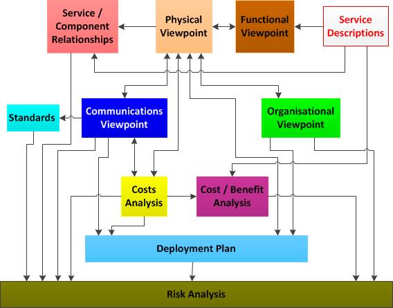
There are relationships between each of the above as well as between each of them and the contents of the ITS architecture itself and with the service descriptions. These are shown in the diagram below.

As can be seen from the diagram, some of the relationships are two-way and the architecture may need revising to create the optimal system configuration as a result of analysing different aspects of the planned implementation. One of the benefits of creating an ITS architecture is being able to do this at an early stage before any contracts have been placed for equipment and communications to be designed and/or purchased.
For some ITS architecture practitioners the creation of a Concept of Operations (or ConOps) document is a key part of the ITS architecture creation process. Its usefulness depends on how the ITS architecture is going to be used and the content of both the functional and physical viewpoints.
The ConOps document can be used to provide answers to stakeholders' questions about what is needed, how it works, who is involved and when it is needed. In order to produce this document, the starting point must be the service descriptions produced at the start of the ITS creation process. And it is for this reason that some ITS architecture practitioners believe it should be produced before the viewpoints and views are created. Indeed it can be used as a mechanism for creating the initial view of the functionality before it is put into the functional viewpoint. However if this is done, the ConOps document should only be regarded as "work in progress" and not considered "final" until the other viewpoints and views have been produced.
Once the service descriptions have been produced and included in the ConOps document, it can be used to provide answers to the following questions:
The information used to answer these questions will be included in the functional, physical, communications and organisational viewpoints. As already noted, this information can be written into the ConOps document as these viewpoints are produced, so long as it is updated after they have been finalised. Alternatively the ConOps document can be produced towards the end of the ITS architecture creation process.
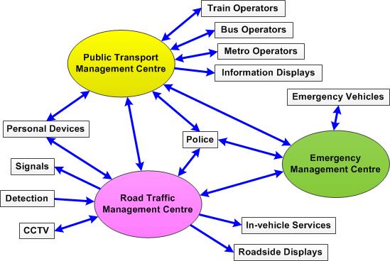
The ConOps document can provide a joined up view of how the services will operate that is not directly provided by the other results of ITS architecture creation. It can also include a diagram to illustrate at a high-level the way that the main components and entities outside the ITS architecture will interact. In practice this diagram will be a combination of the context diagram showing the system boundary and the top level physical viewpoint diagram and could be as shown below.

Like the ITS architecture itself, the ConOps document must not include references to any technology that could be used, or that will need to be developed for the implementation of the service(s) it describes. This is because one of the users of the document will be the stakeholders for whom it can provide a view of how the people creating the ITS architecture believe the service will work. Thus it will be important to get the stakeholders to agree the content of the ConOps document before proceeding to the "Procurement" stage.
Once the stakeholders are happy with the ConOps document its other group of users is the component developers and communications providers. For them it provides the joined up view of how services are to be provided. Therefore and the inclusion in it of any suggestion about technologies to be used will act as a constraint on their design work.
An issue often raised when planning ITS implementations, is how to deal with pre-existing investment in ITS components and communications. The ITS deployment plan produced from the ITS architecture will need to show how these legacy systems are incorporated.
The architecture will inform an analysis of the suitability of any existing ITS components and communications under the following three headings:
In order for these categories to be applied an audit review (inventory and performance appraisal) of existing ITS related components and communications will need to be completed. This is a useful exercise in itself, since it may reveal equipment/installations of which people were unaware or which are at unforeseen locations. An audit of this type is not part of the ITS architecture creation process but is an important part of major new ITS deployments – and can be carried out by people outside the architecture team (See Resources).
ITS is continually evolving as the travel needs of people, organisations that move goods and other travel related organisations continue to develop. Maintenance is important for the ITS architecture to remain relevant - but often overlooked as there is little enthusiasm to allocate the funds to do it. Some form of a maintenance plan needs to be put in place with an appropriate budget. The size of this budget will depend to some extent upon the number, scope and complexity of the ITS services that the architecture includes. But a very rough guide for budget forecasting purposed is that it should be 10% of the total development cost.
The maintenance plan does not need to be onerous, but it should enable a review of the ITS architecture to be made about once every 12-18 months - or less frequently if the architecture has already been adapted to reflect significant changes to the ITS services. The purpose of the review is to see if any new services need be added to the ITS architecture and deployment plans. This requires discussion about the services currently provided and whether stakeholders want them to be revised, upgraded, or new services added (taking account of the features and performance of services provided elsewhere).
If changes need to be made to the ITS architecture, the maintenance plan should provide for its update, following the same sequence of steps as when a new architecture is created (See How to create an ITS Architecture).
When an ITS architecture is updated, the principle of "backwards compatibility" must be followed in relation to any new ITS deployment. The intention is that any changes do not invalidate any developments from the existing ITS architecture. This means that the identifiers for component and communications links should only be re-used in the updated ITS architecture if their characteristics and functionality remain unchanged. So for example if as part of the updating process, the functionality in a component is modified, it must be given a new identity (number and name) as must the revised functions. Similarly if the external source or destination of any communications link, or the data it transfers is changed, the link must be given a new name.
This discipline is most important for framework ITS architectures and is a feature of every new version of the FRAME Architecture. So in parts of the FRAME functional viewpoint, the function numbers start at a value other that 1. For example in functional area 5 the first function number is 5.11; elsewhere there are apparently missing numbers in the sequence – for example in functional area 2, the function numbers are 2.1.2, 2.15, 2.1.7, 2.1.8 and 2.1.9.