
Intelligent Transport Systems (ITS) are a product of the revolution in information and communication technologies in the digital age. Today ITS supports the operation of transport networks that are integrated between road, rail, waterways, ports and airports. ITS also supports the control of vehicles that operate on those networks and efficient planning of the transport operations that use those vehilces (including individual journey planning and vehicle fleet logistics).
Intelligent Transport Systems include a wide range of user support functions, ranging from simple information alerts on a mobile phone through to highly sophisticated traffic control systems. To achieve its functions, ITS utilises a wide range of enabling technologies. These include:
At the heart of any Intelligent Transport System are the twin concepts of information and control technologies. Control technologies support many ITS applications and can be divided into two broad categories:
On the information side, technologies are needed to acquire data, process and fuse the data, make sense out of the data, and disseminate information to the users – including the travelling public. The information collected and processed can also be used to implement control and management measures aimed at improving network performance. ITS enabling technologies also collect real-time traffic and environmental data from the field and transfer the data collected to a central location where the data is processed, fused, analysed and used to support decision-making.
As with control technologies, detection technologies fall into two groups:
The fundamental requirement of Intelligent Transport Systems is data and information about the transportation network (roads and highways). Data needs to be reliable, up-to-date, readily accessible and sufficiently comprehensive for planning and operational purposes. This is the “info-structure” upon which so many ITS applications depend. Base data is usually map-related and held in digital format such as a database of road links that connect known locations, or “nodes” on the network – each with a unique reference. (See Planning Procedures)
As an absolute minimum, network information will consist of a “gazetteer” (or index) that holds the codes and short descriptions of the road links, nodes and other locations, such as:
A network gazetteer can provide a basis for a navigation database if it is sufficiently detailed. (See Navigation and Positioning)
The type of inventory required for ITS equipment and assets deployed across the network will be determined to a great extent by local operational requirements and the ITS applications to be maintained and supported. Information about the ITS equipment and its location will require some form of data management system and an appropriate method of location referencing to support the spatial representation of information. Maintenance Management Systems (MMS) and Communications Management Systems (CMS) are relational databases that can be used to maintain an inventory of ITS equipment and the associated communications infrastructure. Sometimes a performance monitoring system and/or a fault detection system is included. This monitors critical aspects of the equipment or system performance and issues alerts to the maintenance contractor when faults are detected. this monitoring equipment may be referred as Outstation Monitoring Units (OMUs) or a Performance Monitoring System (PMS).
Building on the network description, and using whatever location referencing system is adopted, a variety of data will contribute to the intelligence base for Road Network Operations. They include for each road link:
The network intelligence base needs to be kept current and up-to-date, taking account of any significant modifications to the road network that are:
Where network operations are well-developed a comprehensive database will be maintained of future events likely to have an impact on network capacity. This will require consultation with key stakeholders such as local authorities and the emergency services. (See Planning and Reporting)
Further layers of network information will be generated by the traffic monitoring systems. Data from traffic monitoring has three primary functions in network operations:
These basic functions will be served by information available from a variety of sources – and a systematic approach to traffic monitoring will be needed. An organised, planned approach is essential, especially if the data is going to be used for:
Automatic traffic monitoring systems will supply data in real time on traffic volumes, vehicle speeds, point-to-point journey times and, in some cases, vehicle classification. This data needs to be time-stamped and stored with reference to the link(s) to which they relate, together with a record of the data source. (See Traffic and Network Status Monitoring)
Computer models of the road network are used to forecast future traffic conditions and predict journey times. Modelling makes use of data on link characteristics, junction capacities and whatever traffic and incident-related data is available – which may be dynamic in real-time or historical. Model estimates can be compared with results from traffic monitoring to aid calibration and validation. A network model can also be used to forecast the effects of a given traffic management strategy and identify the potential benefits of that strategy compared to a “do nothing” scenario or an alternative response plan. Modelling can also perform risk assessments or sensitivity testing around different response plans.
Network modelling is able to deliver more efficient strategic traffic management by validating the decisions taken, and by providing better information for network management planning purposes. It can also help provide enhanced travel information for road users, such as more accurate journey times and forecasts of traffic conditions. (See Traffic Models)
Different methods are used to provide location information depending on the technology that is available and the accuracy required. Many countries have an established national grid referencing system which needs to be interpreted to give global latitude and longitude coordinates. Examples of location referencing include global positioning and the Radio Data System Traffic Message Channel (RDS-TMC).
Global positioning (Latitude/Longitude)
Global Positioning Systems (GPS) provide a means for determining an object's location, in terms of latitude and longitude, based on signals received from multiple Global Nautomatic gation Satellite Systems (GNSS) – for example GPS satellites at the location of the GPS receiver. Besides location, GPS can be used to track vehicles and can provide effective fleet management and monitoring the progress of a vehicle along its route.
Radio Data System Traffic Message Channel (RDS-TMC)
Some countries – mostly in Europe – have invested heavily in location referencing for digital radio, known as the Traffic Message Channel (TMC). Using RDS-TMC technology only 16 data bits (the smallest unit of data in computing) are allocated to location coding. This means that the RDS-TMC location code tables are only able to refer to significant highway junctions (nodes) and lengths of road (links). (See http://en.wikipedia.org/wiki/Traffic_message_channel)
ITS systems typically use multiple servers for the different applications, workstations, and video displays in traffic control centres. The computer hardware plays a major role in any ITS system. It is responsible for:
In addition to computer hardware, some ITS applications (such as freeway and incident management systems) typically include graphical displays in the control centre to provide a visual description of the transport systems operations, captured from field cameras.
Graphics can be provided on the monitors of control room workstations, or on large graphics screen displays in the form of a video wall. These displays provide the main “window” (or view) into the traffic management system – and are usually based on a graphical representation or map of the highway network. They will show the on-road assets available for network monitoring and traffic control, such as signals and VMS, location of Emergency Roadside Telephones (ERTs) and CCTV cameras.
Software and relational databases are required for ITS technologies to store, manage and archive network data. These are brought together as Archived Data Management Systems (ADMS) or what is sometimes called ITS Data Warehouses. ADMS offers an opportunity to take full advantage of the travel-related data collected by ITS devices in improving transport operations, planning and decision-making at minimal additional cost.
The technologies supporting ADMS are designed to archive, fuse, organise and analyse ITS data and can support a wide range of very useful applications such as:
The figure below shows an example of the system architecture designed for a simple ITS Data Warehouse being developed for the Buffalo-Niagara region in New York State USA. At the core of the system is a relational data base (such as Oracle or MySQL) which receives data from a wide range of sources including real-time traffic data (volumes, occupancies and speed), incident information, travel time and delay information, weather data, construction and work-zone information, and transit data (such as automatic vehicle location data). The relational database organises and fuses the data and information together – linking the different data streams through common identifiers – allowing a wide range of applications to be developed and deployed.
")
System architecture designed for a simple ITS Data Warehouse (Buffalo-Niagara Region New York State USA)
Among the data stored in ADMS are transport system inventory data, which can be used to facilitate the construction of detailed network models and traffic simulation models. Every link and associated junction in the network will need to be classified according to its strategic importance and capacity. Many ADMS are provided with functionalities that can convert the stored data into the required format for running different traffic simulation and analysis software.
A key benefit of having an ADMS is the ability to quantify network conditions in terms of travel times, speeds and traffic volumes. These measures, based on real-time traffic data, can be used to provide dynamic status information of prevailing network conditions and the “level of service” offered to road-users. Historical data of this kind, including information for incident detection and management and for traffic modelling, can also provide the basis for traffic forecasting and predictive information.
Tree-building algorithms:
Almost all ADMS now include a web-based graphical interface to support users’ queries. The interface is commonly based on Geographic Information Systems (GIS) technology. GIS comprise a set of computer software, hardware, data, and personnel – that store, manipulate, analyse, and present geographically referenced (or spatial) data. GIS can link spatial information on maps (such as roadway alignment) with attribute or tabular data. For example, a GIS-digital map of a road network would be linked to an attribute table that stores information about each road section on the network. This information could include items such as the section ID number, length of section, number of lanes, condition of the pavement surface, or average daily traffic volume. By accessing a specific road segment, a complete array of relevant attribute data becomes available.
The Graphical User Interface (GUI) shown in the ADMS architecture diagram above shows that the data archived in the ADMS can be accessed by different stakeholders over the Internet. Custom applications and reporting functions may be designed including performance measurement, predictive traveller information, traffic simulation model development support, and many other applications.
One of the primary functions of a road or highway network is to allow the safe passage of people and goods from their origin to their destination. Traditional sources of information (printed road maps, direction signs, route listings and journey plans) all have their place but satellite navigation systems are now used widely. Generically these are known as Global Navigation and Satellite Systems (GNSS). Specifically, they include the Global Positioning System (GPS) developed by USA, GLONASS, the Russian global satellite navigation system and GALILEO, the civilian global satellite navigation system being developed by the European Union from its precursor, the European Geostationary Navigation Overlay Service (EGNOS) (See Video).
The USA’s GPS consists of 24 satellites that are deployed and maintained by the US Department of Defence (USDoD). Originally, the system was used solely for military purposes, but since 1983 the USA has made GPS available for civilian purposes. For location determination (longitude, latitude, and elevation), a GPS receiver needs to receive signals from at least four satellites (signals from the fourth satellite are needed to correct for errors and improve accuracy).
A GPS on-board a vehicle – or a smart-phone with a GPS – can determine the location of the vehicle. The location can then be communicated via wireless communication to a central location (such as a traffic operations centre) for processing and data fusion. Besides pinpointing the location of a vehicle and communicating that location to a traffic operations centre, GPS receivers are at the core of all navigation-aid devices developed by companies such as Garmin, TomTom, and Magellan. For navigation and turn-by-turn directions, accurate digital maps are needed, in addition to the GPS receiver.
For its operation, the USA’s GPS relies on signals transmitted from the 24 satellites orbiting the earth at an altitude of 20,200 km. GPS receivers determine the location of a specific point by determining the time it takes for electromagnetic signals to travel from the satellites to the GPS receiver. A limitation of GPS is that it cannot transmit underground or underwater and signals can be significantly degraded or unavailable in urban canyons, in road tunnels and during solar storms. This is why there is continuing interest in terrestrial based radio-positioning systems using technologies such as mobile phones, Bluetooth and Wi-Fi.
GALILEO is the first complete civil positioning system to be developed under civilian control, in contrast to the USA’s GPS and the Russian Glonass systems. GALILEO has been designed with commercial and safety-critical applications in mind, such as self-guided automated cars. The first satellite was launched on 21 October 2011 and the system is scheduled to be fully operational before 2020. When fully deployed GALILEO will consist of 30 satellites (27 operational plus 3 back-up), circling the earth at an orbit altitude of 23,222 km. GALILEO will be fully interoperable with GPS and GLONASS and is expected to achieve very high levels of service reliability and real-time positioning accuracy not previously achieved.
![Figure 3: The European Galileo satellite constellation [European Space Agency]](/sites/rno/files/public/wysiwyg/import/intelligent-transport-systems/1439558854html_html_m763d5216.jpg "Figure 3: The European Galileo satellite constellation [European Space Agency]")
Figure 3: The European Galileo satellite constellation [European Space Agency]
Digital maps are a pre-requisite for satellite navigation and many other ITS applications, such as automated driving and traveller information systems. Many technologies are currently available for creating and updating digital maps. For example, digital maps can be created by collecting raw network data, digitising paper maps, from aerial photographs and other sources. An initiative called OpenStreetMap (http://www.openstreetmap.org) intends to develop digital mapping for the whole world. The maps are developed from GPS traces collected by ordinary people and uploaded to the website. Aerial imagery and low-tech field maps are often used to verify that the resulting maps are accurate and up to date.
A navigation database is a commercially developed database used in satellite navigation systems. It is often based on a Network Gazetteer (See Basic Info-structure) and will contain all the elements needed to construct a travel plan or a route from a specific origin to a specific destination. Additional criteria may be added such as the route passes through a specific point, that it avoids tolls, that it is the fastest or shortest available, or that it minimises fuel consumption or emissions.
A navigation database is multi-layered and requires more than the basic coordinates for the road network links and nodes, although that is an important starting point.
Additional features necessary for navigation include:
Navigation databases also contain information on points of interest and landmarks, such as public transport facilities, major office buildings by name, hotels, restaurants and tourist attractions, post offices, government buildings, military bases, hospitals, schools, petrol stations, convenience stores, shopping centres and malls, toll-booths – and in some countries, the location of speed cameras.
Crowd-sourcing and social networking has enabled the creation of navigation databases that are adapted to the needs of specific groups of road-users, such as truck drivers and cyclists. There are also important developments taking place in pedestrian navigation.
Infromation on pedestrian navigation: http://www.insidegnss.com/node/513 and http://www.navipedia.net/index.php/Pedestrian_Navigation
Location-based services are computer applications that use location data to control features or the information displayed to the user. They have several applications in health, entertainment, mobile commerce, and transport. In road transport, for instance, location-based services can be used to provide point of interest information (using data held in a navigation database – such as the closest fuel station or restaurant. Location-based services can also be used to display congestion or weather information according to the location of the user (See Location-Based Services).
In co-operative systems, vehicles share data with each other and with the road infrastructure using vehicle to vehicle (V2V) and vehicle to infrastructure (V2I) communications. Vehicles that are connected in this way can make use of real-time information on moving objects (such as other vehicles nearby), and on stationary objects that might be transitory (traffic cones, parked vehicles and warning signs). This highly detailed, constantly changing information is held in a data store known as a Local Dynamic Map (LDM). The LDM supports various ITS applications by maintaining information on objects that influence, or are part of, the traffic. Data can be received from a range of different sources such as vehicles, infrastructure units, traffic centres and on-board sensors. The LDM offers mechanisms to grant safe and secure access to this data by means of V2V and V2I communications.
The data structure for the LDM is made of four layers:
Location referencing and object positioning for the upper layers of the LDM is complex and requires adequate location referencing methods. Since not all ITS applications need location referenced information, the use of this data is not mandatory.
These technologies allow the location of vehicles to be ascertained in real-time as they travel across the network. AVL has many useful applications for vehicle fleet management, such as improving emergency management services by helping to locate and dispatch emergency vehicles. AVL can be used for probe vehicle detection and on buses to locate vehicles in real-time and determine their expected arrival time at bus stops.
A number of technologies are available for AVL systems including dead reckoning, ground-based radio, signpost and odometer, and Global Positioning Systems. GPS is currently the most commonly used technology.
Another system for tracking and locating vehicles uses fixed point transponders which can read and communicate with other equipment – for example, toll tags on-board vehicles. These systems can determine when a vehicle passes by a certain point, and provide useful information on travel times and speeds.
A third method for locating vehicles is through mobile phone triangulation. The location of a mobile phone user is identified by measuring the distance to several cell phone towers within whose range the user is located. Using this technology, the location of the vehicle can be identified within an accuracy of about 120 meters. In rural areas, where few cell towers are located, the tower can measure the angle of transmission, which – along with the distance – can be used to locate the phone user even though the user might only be within the range of single cell phone tower. The estimated location in this case is not very accurate (within about 1.6 km).
A pre-requisite for Road Network Operations is the collection of accurate data that defines the status of road network, the traffic conditions that prevail and information about roadway conditions and the immediate environment. (See Planning Procedures) Data on traffic and weather conditions, incidents and other road and highway status alerts is used to provide intelligence for network operations activities, traffic control and information systems. This process of gathering data is called network monitoring, and can be undertaken by using a variety of means or a combination of them:
The extent and reliability of monitoring directly affects the amount of information available to plan operational activities and, in turn, the degree of management and control that is possible. It also determines the quality of information that is available to travellers and road users. (See Network Monitoring)
A number of steps are involved in the organisation of data processing and information supply. Together they form an information supply chain.
The first step is to acquire data about the status of the road network and the traffic using it, as well as other transport modes that connect with it. This data can come from a wide variety of sources including probe vehicles and roadway sensors such as inductive loops and microwave sensors, Closed Circuit TV (CCTV), webcams, video image processing, toll tag readers. It can be augmented with other information gathered from crowd sourcing and journalistic sources. Data mining techniques are applied to historical data to gain further insight into traffic operations and to provide predictive information on network conditions. (See Traffic & Status Monitoring)
Once the data is collected, the next step is to process it in ways that will yield useful information. This covers a number of basic functions:
The third step relates to the data analysis. This requires an appreciation of contextual relevance, processing of content to produce information according to user needs and preferences – including formatting the data for service. Data needs to cover the geographical area of interest and be checked for timeliness. Key issues are:
To provide predictive information, various time series analysis, data mining, mathematical modelling and Artificial Intelligence (AI) methods are used (See Data Aggregation and Analysis).
Various methods are used to disseminate the data that has been collected, processed and analysed. A variety of transmission media are available. For example, incident warnings and travel information is provided via many dissemination media, including data subscription services, travel news broadcasts, Highway Advisory Radio (HAR), roadside Variable Message Signs (VMS), internet websites and social media such as Facebook and Twitter. The security and integrity of transmission needs to be checked and maintained at all times. (See Traveller Services)
Information needs to be presented appropriately in response to user needs and the context of use. Good design of the user interface is essential. In traffic control centres, data may be displayed alongside CCTV camera images on a video wall or on-screen at operators’ work stations. Other stakeholders and the travelling public will use a range of devices to access information – such as desktop, laptop and tablet computers, mobile devices and smartphones, in-vehicle displays, public information points and kiosks. (See User Interfaces)
Issues may arise related to data ownership and intellectual property in respect to the use of public sector data versus commercial and proprietary data, information branding, value-capture, revenue and payment. (See Legal and Regulatory Issues)
An effective (and often extensive) traffic surveillance and monitoring system is a pre-requisite for any intelligent traffic control system to keep track of prevailing conditions across the network. A wide range of different sensors are installed in, on and above the roadway for this purpose and to obtain the necessary geographical and critical time coverage. They include inductive loops, non-intrusive traffic detection devices, video cameras and video image processing. Each technology has its own advantages and shortcomings – so the choice of sensor type for any ITS application will depend on what performs well in the prevailing environmental conditions, and its cost.
Traffic detectors (or vehicle presence detectors) are used in many ITS applications for – network monitoring, traffic control, speed measurement and automatic incident detection. Many different types of detection technologies are available. The following are typical technologies that have been developed to measure traffic data in specific locations and zones. (See Vehicle Detection)
Inductive loop detectors are currently the most widely used devices for vehicle detection, although microwave radar detection is also common. Their main uses are at intersections in conjunction with advanced signal traffic control systems, and on freeways for traffic monitoring and incident detection purposes. ILDs typically take the form of one or more turns of insulted wire embedded in the pavement. The loop is connected via lead-in cable to the detector unit, which detects changes in the loop inductance (changes in the in the magnetic field of the sensor) when a vehicle passes over it. ILDs can be used to detect a vehicle’s presence or passage. They can also be used to measure speed (by using two loops a short distance apart) and for classification of vehicle types. The main problem with using ILDs, however, is their reliability. Because ILDs are subject to the stress of traffic, they tend to fail quite frequently. Moreover, their installation and maintenance require lane closure and modifications to the pavement.

Inductive Loop Detectors
Microwave radar detectors are examples of non-intrusive detection devices whose installation and maintenance does NOT require lane closure and pavement modifications. Unlike inductive loops, non-intrusive detection devices are not embedded in the pavement. Instead, they are typically mounted on a structure over, or to the side of, the road such as the radar detection system in the photograph below. Depending on the type of electromagnetic wave used, microwave radar detectors can measure either vehicle presence, or vehicle presence as well as speed. They are also widely used to detect pedestrians waiting at pedestrian crossings.
One of the major advantages of microwave sensors is their ability to function under all weather conditions. Exceptions can be extreme weather such as sand-storms. Given that these sensors are installed above the pavement surface, they are not typically subject to the effects of ice and ploughing activities. Experience shows that microwave sensors function adequately under rain, fog, snow, windy conditions. Their main problem is that they can be obscured by tall sided vehicles – reducing their accuracy when they are installed at the side of the carriageway.
")
Non-intrusive Traffic Detector (Image courtesy of the IBI Group)
Infrared (IR) sensors are also non-intrusive detection devices. There are two types: passive and active detectors.
Passive IR detectors do not transmit energy – instead, they detect the energy that is emitted or reflected from vehicles, road surfaces and other objects. Passive infrared detectors can measure speed, vehicle length, vehicle counts and occupancy but their accuracy is affected by adverse weather conditions.
Active IR detectors emit a beam of Infrared energy which is reflected back to an IR receiver. They function in a similar way to microwave radar detectors – by directing a narrow beam of energy towards the road surface. The beam is then reflected back to the sensors – and vehicles are detected through changes in the “round-trip” transmission time of the infrared beam. Active infrared detectors supply vehicle passage, presence, speed, and vehicles classification information. They work well in controlled environments such as tunnels – and infrared can be used for safety purposes to detect over-heating vehicles or fire. Their accuracy is affected by weather conditions such as fog and precipitation.
Ultrasonic vehicle detectors function in a similar way to microwave detectors by actively transmitting pressure waves, at frequencies above the human audible range. These detectors can measure volume, occupancy, speed, and classification. Ultrasonic sensors are sensitive to environmental conditions. They require a high level of skill for their maintenance.
Vehicle traffic produces acoustic energy or audible sound from a variety of sources within the vehicle and from the interaction of the vehicle’s tyres with the road surface. Using a system of microphones, acoustic detectors are designed to pick-up these sounds from a specific area within a lane on a roadway. When a vehicle passes through the detection zone, a signal-processing algorithm detects an increase in sound energy and a vehicle presence signal is generated. When the vehicle leaves the detection zone, the sound energy decreases below the detection threshold and the vehicle presence signal ends. Acoustic sensors can be used to measure speed, volume, carriageway occupancy and presence. The advantage of acoustic sensors is that they can function under all lighting conditions and during adverse weather.
Similar to inductive loop detectors (ILD), magnetometers provide for point detection, but they differ from ILD in that they measure changes in the earth’s magnetic field resulting from the presence of vehicles. They can provide information on traffic volume, lane occupancy, speed as well as vehicle length. In general, there are two types of magnetometers:
Micro loops, (like inductive loops), require lane closure and pavement modification, with consequent delays to traffic. In recent years, the use of wireless magnetometers has received increased interest because of advances in battery technology which allow a unit to operate wirelessly for a period of 10 years before needing to be replaced.
Traffic Detector Video Training Course - Part 1 - Detector Theory
Traffic Detector Video Training Course - Part 2 - Detector Design
Traffic Detector Video Training Course - Part 3 - Detector Installation
Traffic Detector Video Training Course - Part 4 - Detector Maintenance
AVI can be used to identify vehicles as they pass through a detection zone. Typically, a transponder (or a tag) mounted on the vehicle can be read by a roadside reader as the vehicle passes by. This information can then be transmitted to a central computer. Currently, the most common road transport application of AVI technologies is in combination with Automatic Toll Collection systems (such as EZPass). With these systems, the value of the toll is automatically deducted from a driver’s account each time the driver goes through the toll plaza.
An important method of AVI, in common use, are ANPR (also known as Automatic Licence Plate Recognition - ALPR) systems which use optical character recognition technologies to identify and recognise vehicle registration plates. They typically consist of a specially adapted video camera linked to character recognition software. As a vehicle passes an ANPR/ALPR camera its registration number is read and can be checked against a database of vehicle records. There are two broad types of ANPR/ALPR systems:
With recent advances in computer hardware and software – processing in the field in real-time has become quite feasible (it typically takes less than 250 milliseconds). This avoids the cost associated with the need for large bandwidth to transfer images to a remote server.
Weigh-in-motion sensors are designed to measure and record axle weights and gross vehicle weights while the vehicle is in motion (driving – not stopped). WIM systems are attractive because they avoid the need to stop and weigh every vehicle. They have not eliminated the need for weighbridge sites for accurate weighing of trucks, but WIM acts as a filter and only vehicles which register an excess axle load need to be stopped and checked. The key component of any WIM system is the force sensor – for example quartz crystals produce electric charge when a force is applied along the vertical axis (the weight of the vehicle). WIM systems have several applications in ITS, especially as a part of an electronic pre-clearance system for commercial vehicles, as well as for enforcement applications. (See Enforcement and See Video)
Speed detection is an integral part of speed camera enforcement systems used to detect speed-related violations of traffic rules especially at accident hot spots. (See Speed Management) Regulation of speed is important at work zones where personnel are at increased risk of an accident. It is also a feature of active traffic management schemes on motorways. Some speed enforcement systems automatically link speed cameras to vehicle number-plate (Licence-plate) recognition for issuing enforcement notices. (See Traffic Management and Integrated Strategies) Speed detection can also be used as a safety measure at signalised intersections on fast arterial roads by using microprocessors to extend the green time at traffic signals when a vehicle is approaching at speed.
For measuring speed, the most common device is a radar meter or sensor which uses the Doppler principle. Specifically, the device measures the difference in the emitted and reflected frequency of a radar wave – which is proportional to the speed of the moving object. Other types of vehicle sensors can be adapted in pairs to measure speeds – such as ultrasonic sensors and magnetometers.
Journey time monitoring is related to speed monitoring. Vehicle journey times are significant sources of information for network performance monitoring and advising road users about travel delays in real-time. They are a measure of the level of service on offer. Some road authorities display point-to-point journey times on roadside VMS as a form of real-time information. Journey time data (historic and in real-time) is also a useful resource for journey planning and logistics support. (See Journey Time Monitoring)
Various methods are available to anonymously track vehicles on the network and enable network operators to determine average travel times, point-to-point demand and traffic flow conditions. For example, Automatic Toll Collection (ATC) systems can be used to determine the average travel time on highways between toll collection plazas or specially installed roadside readers. Infra-red (IR) tag-equipped vehicles are used as probes for monitoring traffic flow conditions – which are detected by transponder readers, installed along roadways. Aggregate data on average speeds and travel times can be compiled and this helps support incident and traffic management. To protect travellers’ privacy, these systems scramble the toll tag identifiers and only keep records of trips made by anonymous vehicles.
A number of other techniques are used to provide continuous, non-invasive, point-to-point tracking of individual vehicles to determine travel times and calculate average speeds. They include automatic number-plate recognition cameras (ANPR cameras) to identify vehicle licence plates. A new development is point-to-point monitoring of Bluetooth signatures emitted by equipment present in the vehicle. Bluetooth sensors have been used successfully for point-to-point average speed monitoring as a cheaper alternative to ANPR. Some road authorities use aggregated data (made anonymous) to display on VMS to provide drivers with expected journey times between key points on the network.
Environmental sensors are used in road network monitoring to detect adverse weather conditions such as icy or slippery conditions, high winds or precipitation (snow or rain) or the presence of fog/mist. This information can then be used by operators to alert drivers via variable message signs (VMS). It can also be used by highway maintenance personnel to optimise winter maintenance operations. (See Weather Monitoring)
Environmental sensors can be divided into six types:
Many manufacturers provide complete weather station systems that are capable of monitoring a wide range of environmental and surface conditions. The figure below shows one example of these weather stations.
(Figure 4.7 to be located here – to be supplied by the author)
Weather stations typically include the following types of sensors and capabilities:
Road condition sensors: A critical component of any road weather information system (or RWIS) is a set of road condition sensors that measure surface temperature and moisture, and detect the presence and thickness of snow and ice. Road condition sensors can be embedded in the pavements. They can also be non-intrusive – mounted to side or above the road surface. Non-intrusive road condition sensors typically measure the emitted infrared radiation from the road surface.
Visibility sensors: These sensors are designed to measure visibility along a road section. They typically use the principle of “forward scattering” or diffraction of light to detect changes in visibility resulting from inclement weather conditions such as fog, haze, and smoke. The sensors need to be carefully sited because they can only provide spot measures at a specific location. For example, fog detectors need to be sited as near as possible to the source where mist or fog forms first.
Thermal mapping: Given that temperatures can vary significantly along a roadway segment, thermal (temperature) mapping sensors are typically a critical component of an effective ice detection system. Thermal mapping provides road operators with information on road-surface temperatures to inform decision making on the need to set-up warning messages on VMS or to deploy snow clearance, road salting and gritting services. Examples of thermal imaging sensors include thermal imaging cameras/ video and infrared thermography.
Wind speed sensors: These are an essential component of an environmental sensing station and are installed at high and exposed bridges and windy locations on the road network. They typically measure surface wind speed and direction and can be used to provide warnings to vehicles towing trailers and high-sided vehicles. For safety reasons it is sometimes necessary to close the road in high winds.
Mobile reports can be divided into two categories:
In many cases, reports of incidents made by citizens and the police can provide significant road network monitoring information – and at a very low cost compared to other surveillance technologies. Mobile reports do not provide a continuous stream of condition data provided by other surveillance technologies, but they so provide event information at unpredictable intervals that are very useful for traffic management purposes. In particular, mobile reports are very effective for incident detection.
A number of different mobile reporting methods are used in road network operations.
Cell phones are a very effective tool for incident detection. Many regions have established an incident reporting hotline to encourage citizens to report traffic incidents. This has the advantage of low start-up costs.
The widespread use of cell phones can provide useful traffic information. Triangulation techniques can determine a vehicle’s position by measuring signals from an on-board cellular phone within the vehicle. To enable this, the cell phone needs to be communicating with more than one cell-phone cell – preferably three or more for accuracy – so that triangulation can take place. Each phone is typically identified by its electronic serial number. This concept was first tested in the Washington D.C. area in the mid 1990s. This concept is different from GPS-based AVI systems in which the GPS unit on the phone determines the location, which is then communicated from the phone to a central processing system.
Emergency Roadside Telephones (ERTs) were regularly provided prior to mobile telephones becoming widely available. ERTs still provide a valuable service where there is a low ownership of mobile telephones or a mobile-phone black spot. They provide an accurate location to the operator of where a caller is located and enable stranded motorists to call for help. More generally, they allow travellers to report incidents such as accidents or stray animals on the carriageway.
To use a call box, the motorist just needs to lift the receiver or press a key to request the services of the police or emergency services. The caller is automatically connected to a control room operator.
Advanced types of ERTs provide background noise cancellation against traffic noise, and a simple question and answer facility based around «yes» and «no» keys for the profoundly deaf and foreign travellers. The Operator has a formal list of questions that they can ask in sequence by typing in the questions. The questions appear on a small screen at the ERT and the user answers using the yes and no keys. The option to select different languages is a great advantage near ports and border crossings where there is a high percentage of foreign visitors. They also have a call-back facility that enables the operator to call the stranded motorist, with a beacon and ring tone to attract attention.
Typically, the phones are located on the side of the freeway, and are spaced at distances ranging from 0.25 miles to 0.50 miles apart. On all-purpose dual carriageway arterial roads, freeways and motorways they need to be located in pairs on either side of the road to avoid travellers being tempted to cross the road to use one.
(Figure 4.5 Call Box – Image to be provided by Barry Moore)
These are teams of trained officers who are responsible for covering a given segment of the freeway. Mobile patrols have a central part to play in road network operations, spotting debris on the road, dealing with incidents and the general public. A freeway service patrol vehicle [Figure 4.6] is typically equipped to be able to help stranded motorists and, where possible, to clear an incident site. Mobile patrols are capable not only of responding to incidents, but in some cases to perform the entire incident management process (from detection to clear-up).
Technology, in the form of secure mobile communications and hand-held tablets, provides support. TETRA mobile radio communications offer digital transmission capability whilst maintaining the advantages of a Private Mobile Radio (PMR) system. In future service patrols may have command and control capability to direct and manage the deployment of on-road resources – and the potential to set VMS and signals on location, remotely from the road side.
Figure 4.6 A Freeway Service Patrol Vehicle
A relatively new technique for collecting traffic-related information based on mobile reports is crowdsourcing – using social networks such as Facebook and Twitter. Crowdsourcing is the process of obtaining information online that is provided by a crowd of people. This method has become feasible in recent years because of the significant developments in positioning and communications technologies that are linked to mobile phones which have internet connectivity. In road transport, crowdsourcing concept can be used to collect vital travel-related information in collaboration with members of a community. One of the most famous and successful of these crowd-sourcing applications is WAZE (https://www.waze.com/) – one of the world's largest community-based traffic and navigation apps. Users of WAZE share real-time traffic information, allowing members of the on-line community to save time and fuel while travelling.
Vehicles are used to report journey times and detect traffic incidents – monitoring their progress in time and space. This can be done by either using automatic vehicle location systems or by tracking the progress of identified vehicles between known fixed points on the network. The location of the vehicle in time and space is communicated to a central computer where data from different sources is fused to determine the status of traffic flow over the transport system.
Vehicle probes can provide very useful information that other detection techniques cannot – including information on link travel times, average speeds, and origin-destination information.
Different technologies are available. These include:
Vehicle probe methods give more reliable but less dense data than crowd-sourcing, which may provide better geographical coverage. Vehicle probes are often deployed by road network operators in collaboration with the owners of vehicle fleets that regularly travel the network.
CCTV cameras play an important part in road network management. They are installed at sensitive locations on the network to support traffic management, where congestion and traffic queues are frequent and at other locations where there is an increased risk of accidents and traffic incidents. When used for traffic surveillance they can either have a fixed field of view – for example, when used to monitor traffic and provide alerts – or be equipped with a pan, tilt and zoom (PTZ) capability to allow operators to have a wider field of view.
Fixed field of view cameras are generally used for monitoring motorway sections where hard shoulder running is permitted.
Pan, Tilt Zoom (PTZ) cameras are commonly used for:
Either fixed or PTZ cameras can be used:
Control room operators depend on the CCTV camera images – displayed either on their work-stations or large-scale on a “video wall”. CCTV camera images are an important means of traffic surveillance that complements other traffic control measures. Operators rely on images from CCTV cameras to detect and monitor traffic incidents and assess the number of running lanes affected. From this it may be possible to estimate the likely duration of a traffic incident based on previous experience and traffic modelling techniques. Video image processing is used to alert control room operators to stationary vehicles and other unusual events. Operators often wish to see a sequence of images from successive CCTV cameras, in the form of a “video tour” (See Traffic Control).
 Closed Circuit TV Camera (Image courtesy of the IBI Group)")
Pan, Tilt and Zoom (PTZ) Closed Circuit TV Camera (Image courtesy of the IBI Group)
Video image processing (VIP) identifies vehicles and their associated traffic flow parameters by analysing imagery supplied from CCTV cameras which normally have a fixed field of view. The addition of VIP significantly improves the usefulness of CCTV, particularly where there are a large number of cameras installed, which an operator cannot view at the same time. VIP also provides the means for alerting operators to a traffic incident.
Analogue CCTV images are digitised and then passed through a series of algorithms that identify changes in the image background. In modern digital cameras the video image is already in a digital form – ready for processing. A VIP system consists of a video camera (a digitiser in the case of analogue cameras) and a microprocessor for processing the digital-image – and software to interpret the image content and extract detection information from it.
With digital processing CCTV provides an above-ground alternative to inductive loops or other means of vehicle detection. One big advantage of VIP systems is their ability to provide detection over a number of lanes and in multiple zones within the lane – providing wide area detection. The user can easily modify the detection zones, within seconds, through the graphical interface – without the need to close traffic lanes and dig-up the pavement. Poor lighting, shadows, and bad weather can negatively affect the performance of VIP systems. Evaluation studies in Oakland County, Michigan indicate that modern VIP systems yield excellent performance with a detection accuracy of over 96% under all weather conditions.
VIP systems can be combined with CCTV systems to provide an excellent detection tool, particularly for incident detection and verification purposes. When an incident occurs, the user can switch from the VIP mode to the standard CCTV mode, and then verify the occurrence of the incident via pan/tilt/zoom controls.
An effective interface with users is an essential part of many ITS applications. Users include control centre operators, the police and emergency services, road users and travellers. Many technologies support the dissemination of pre-trip and en-route information. To make traveller information available, historical and current traffic data and status of the network needs to be monitored and processed and put in a format which travellers can easily access (See Travel Information Systems).
Pre-trip traffic information provides travellers with information before they start their journeys. Examples of pre-trip traveller information include information on current or expected traffic conditions, current and expected weather conditions, and information on public transport schedules and fares. It is intended to help travellers to make informed route/mode/time of departure decisions (See Pre-trip Information).
En-route traffic information provides travellers with information while they are travelling. En-route traffic information includes many of the same elements provided for pre-trip planning – but updated in real-time – such as information on current and expected traffic and weather conditions, information on incidents and suggested diversion routes.
ITS uses many traffic information dissemination platforms to keep people informed about current as well as expected travel conditions. These include Dynamic Message Signs (DMS), Highway Advisory Radio (HAR), cable TV, traveller information websites and the Internet, dedicated phone systems, cellular telephone applications – and in-vehicle display. Information dissemination devices can be classified as:
With the proliferation of portable and mobile computing devices – such as smart phones and tablets – this three-way distinction is less clear now than it used to be. These are capable of accessing the Internet while the traveller is en-route – and there may be concerns about driver distraction and regulations against their use in certain circumstances (See Human Factors).
Dynamic Message Signs are also referred to as Variable Message Signs and Changeable Message Signs. In this website the following terminology is used:
A DMS may be either a Variable Message Sign (VMS) or Changeable Message Signs (CMS) where:
DMS are among the most common types of devices for information provision. They can either be fixed or portable as shown below. They can be text-based, graphics based or a combination of the two (See Traffic Management)

Figure 4.12 Fixed Dynamic Message Signs

Figure 4.13 Portable Dynamic Message Signs
DMS can be used to provide travellers with instructions such as closed lanes or recommended speeds and information on traffic and weather conditions, incident locations and expected delays, construction work, alternative routes and speed advisories. Different types of DMS can be light-reflecting, light-emitting, and hybrid according to the technology used. Light emitting diodes (LEDs) are generally the preferred option where there is a power supply (including solar options).
As the name suggests, these rely on an external source of light, such as the sun, headlights, or overhead lighting, to make them visible – by reflecting the light source. Different types of light-reflecting signs include rotating drum and reflective disk matrix signs. Rotating plank/drum signs are made of one to four multi-faced drums, each containing two to six fixed text messages or graphics. The main application of rotating plank/drum technology when it is incorporated into a fixed direction sign – is to provide variable instructions, that are identical in appearance to the fixed sign face, to show an alternative direction to a destination.
Reflective disk matrix signs comprise an array of permanently magnetised, pivoted indicators that are black on one side, and reflective white or yellow on the other. When a specific pixel is activated, an electric current flips the indicator from the black finish to the reflective yellow finish.
Reflective disk matrix signs were popular in 1970s for freeway management systems because they were less costly than light-emitting signs. Mechanical failure of some or the entire message is common (disk failure). As LED signs become less costly the older technology is falling out of use.
These generate their own light on or behind the viewing surface – either in monochrome or full colour. Light emitting diode (LED) and fibre-optic DMS are two examples:
LED has become the preferred technology. New versions of LED DMS provide a display known as a full matrix that can display graphics and images.
Hybrid DMS combine the characteristics of both light-reflecting and light-emitting DMSs. One of the best examples of hybrid DMSs is the reflective disks/fibre-optic or LED DMS. During weather conditions when light-reflecting DMS are not clearly visible, these hybrid systems can use light-emitting technologies such as fibre-optics or LED. When the sun is shining, the light sources are turned off. Solid state LEDs are more reliable than reflective disks since there is no risk of mechanical failure.
In-road markers or lane lights (also known as intelligent road studs) can be used to convey important messages to drivers, in addition to their most direct function of lighting the way at night. For example, in-road markers can be used to communicate the usage of a lane. Intelligent road studs have been used for signing the use of the hard shoulder during periods of heavy congestion, hazard warnings and operation of part-time bus lanes
These devices are typically located inside the vehicle and, similar to DMS, are designed to provide information to drivers while en-route. In-vehicle information devices can provide information by either audio or visual means. Examples of auditory in-vehicle information devices include highway advisory radio (HAR), cellular phone hotlines and commercial radio. Examples of visual in-vehicle devices include video display devices and head-up displays (which drivers can read without altering their normal viewing position
Highway advisory radio (HAR) provides another means for disseminating information to drivers while en-route. Typically, information is provided through an AM receiver. Drivers are informed about the existence of an HAR signal by signs which are typically installed upstream of the signal, advising drivers to tune in to a specific frequency (typically either 530 kHz or 1610 kHz) (See Radio).
HAR can be used to provide travellers with information similar to that provided by VMS. One advantage of HAR compared to VMS is that it is less distracting – since information is provided through a different sensory channel (audio) which reduces visual information overload. More complex messages are also possible with HAR compared to DMS. The disadvantage is that users have to tune to the frequency themselves.
Another way of providing information to drivers en-route, – which has increased in popularity with the widespread use of cellular phones – involves establishing a “hotline” phone system for traffic information that drivers can call from their cell phones while en-route (such as the 511 system in the US). The phone systems typically include a touch-tone menu that allows callers to receive route-specific traffic information – this gives the driver control over the type of information received.
Commercial radio is another means of providing en-route traveller information. The primary disadvantage of commercial radio is the accuracy and timeliness of the information. Typically, information is broadcast only when normal scheduling permits – and in many cases, this may be inappropriate since an incident might have been cleared by the time normal scheduling permits broadcasting.
A recent approach to disseminating traffic information en-route involves the use of dashboard displays, video and head-up display terminals. Close attention to the design of the Human-Machine Interface is needed to minimise driver distraction (See Human Factors).
These technologies are widely used for pre-trip and off-roadway information dissemination. They include cable TV, phone systems, the internet, pagers, smart phones and tablet computers. Many metropolitan areas around the globe now have websites dedicated to traveller information. These systems provide travellers with a wealth of travel-related information, including current travel conditions, alerts, and other timely information. A traffic map showing current speeds, locations of any incidents or construction zones typically form a central part of these websites. Among the technologies used for off-road roadway information dissemination are dynamic public information displays and kiosks – and mobile devices.
Large shopping malls and motorways often have dynamic information displays and kiosks where real-time travel conditions may be provided. This is also true of many motorway rest areas. These displays and kiosks were very helpful before widespread public take-up of mobile computing devices and smart phones. With the advent of these technologies, public information displays and kiosks have played a secondary role in information dissemination. They are still available at many sites and are useful for those sectors of the population who do not have access to mobile computing and smart phones.
The high market penetration of smart phones, tablet computers and personal navigation devices has provided the transport industry with an invaluable tool for disseminating travel information. The unique advantage of these nomadic and mobile devices is that they make travel information available to travellers on a continuous and uninterrupted basis.
Many navigational devices and services include real-time information about the transport network conditions. This is demonstrated by services such as Google maps and navigation – as well as by GPS navigation devices that can receive real-time traffic condition information. Crowd-sourcing is also being used to collect and disseminate travel information.
Telecommunications are an essential part of Road Network Operations and Intelligent Transport Systems. Over the past 40 years they have been developed piecemeal to support network operations – for example by linking control centres with roadside devices such as telephones, CCTV cameras, Variable Message Signs (VMS) and traffic signals. Today digital communications dominate the transmission of voice, video and data signals. Digital technology is inherently more reliable, flexible and manageable compared with previous generations of communications technology. Digital communications enable the development and operation of modern traffic management technology and the latest ITS applications – including connected vehicles and Active Traffic Management. CCTV is used increasingly and digital transmission of video images is possible over distances without the image being degraded.
Telecommunications networks resemble the nervous system in a human body. Specifically, the communications networks tie the different components of ITS together, allowing for a truly integrated system. For example, they provide a data link from the field devices (detection technologies, Dynamic Message Signs, signal controllers) to traffic operations centres – where the collected data is fused, analysed and acted upon. This is illustrated in the diagram below. Telecommunications are also needed to carry instructions and commands from control centres back to field devices for traffic control purposes. They are also the means for infrastructure operators (controllers) relaying information to travellers and stakeholders.
")
National Roads Transmission Network for England (Courtesy of Highways England. In this diagram MIDAS means Motorway Incident Detection Alert System.)
An ITS system will not function without an appropriately designed communications network that has adequate bandwidth and is capable of delivering an adequate level of service (in terms of message delivery, latency and drop-out rates). Decisions on the appropriate communication technology, the appropriate network topology and other communications design issues have to be made carefully. This is because the cost of the communication network typically constitutes a major component of the cost of a specific ITS system. In some cases, where a cable and transmission equipment infrastructure needs to be installed, it can be up to 50%.
There are a number of options for ITS professionals. Traffic operators need to decide how best to meet telecommunication needs and what they are capable of doing. Broadly speaking, the technologies can be divided into wired communications and wireless communications. The choice for roadside installations is often a trade-off between cost and functional capability.
The telecommunications network to support ITS needs to be carefully designed. A common architecture for such networks is known as a hierarchical or layered architecture, which exhibits many similarities to the hierarchical system of road networks themselves. Specifically, telecommunications networks may be regarded as consisting of four layers:
Using highways as an analogy for telecommunications, the backbone layer is similar to the inter-state / inter-urban strategic roads. It enables moving (hauling) large amounts of data between a limited number of fixed distribution points. As with road networks, the different layers of a communication network are interconnected. Fibre optics cables are commonly used for this layer.
The function of the backhaul layer is to move (haul) large amounts of data (which still requires large bandwidth) from the backbone network to the Traffic Control Centre. It is often off the highway/road network – and can be provided by a service provider such as a telecommunications company (TelCo).
The distribution layer resembles the system of arterial roads in a road network. This layer typically does not handle large volumes of data. Its main purpose is to provide multiple points of presence to enhance accessibility.
Finally, the access layer resembles a residential or local street network or the lead/cable which connects the TV to the aerial socket – that provides local cabling to access the different devices on the network.
Another option for transport agencies is to lease wired communications services from a telecommunications company. In earlier years of ITS, some ITS applications (urban control systems) used leased telephone lines – their limitation is the very low bandwidth provided by telephone lines. Today it is becoming increasingly cost effective to use WiFi to replace leased telephone circuits, particularly in urban areas – or as an alternative to costly new cable networks for inter-urban roads when bandwidth requirements are modest.
More recently, new technologies have been developed to help improve the speed of communications on local telephone networks. In particular, Digital subscriber line (DSL) – which uses higher frequency bands for data – can offer speeds of up to 40 Mbits/second. Asymmetric Digital Subscriber Line (ADSL) is a type of digital subscriber line (DSL) technology that enables faster data transmission over copper telephone lines. Another technology is cable internet which uses cable television networks in much the same way as DSL uses telephone lines. Cable Internet could have speeds of up to 400 Mbits/second – and so can support most ITS applications that have demanding bandwidth requirements.
It is often more cost effective to lease dark fibres from a telecommunications operator or buy-in a service rather than install a dedicated system. Leased Communication Systems in ITS are widely used for urban traffic control systems and to provide the backhaul for connecting TMCs to the field communications on a motorway.There are two reasons for this:
Leased communications also provides a means for satisfying the communications needs of rural ITS applications where the installation of new communication lines may be too expensive.
Highways England (a Government owned company) established a public-private partnership to upgrade, operate, and maintain the communications systems that link the roadway communication devices (emergency telephones, CCTV, etc.) along the motorways and other strategic roads in England. A telecommunications consortium was selected for a 10 year project.
The consortium has end-to-end responsibility for voice, data and video transmission services that link the Highways Agency’s roadside devices to the control offices. The roadside devices and control centre applications themselves remain with the Agency. The consortium is responsible for monitoring the performance of the transmission services, for providing a resilient and reliable service and for providing additional local connections to support additional roadside devices.
Wired communications use fibre optic and copper cables to connect roadside equipment to control centres. Typically these cables run in ducts along the motorway or roadway with the necessary data transmission equipment housed in roadside cabinets. The control centres themselves are in strategically located buildings with cable connections to the main network.
Wired communications include a wide range of technologies that vary in performance, cost and bandwidth – meaning the volume of data that they are capable of communicating is variable. At one end of the spectrum there is fibre optic technology that provides the highest bandwidth of any communications system existing today. At the other end are the old-fashioned telephone lines with limited bandwidth for data transfer.
A fibre optics cable is a communications medium for light waves to carry a signal that transfers information from one point to another. The cable itself is very thin (slightly thicker than a human hair). For operations, an optical transmitter is needed at one end of the cable, and a receiver at the other – to convert electrical signals into light signals and back again at the receiving end.
Current fibre optics technology is capable of transmitting about 1.5 Gbits of information per second.
Another advantage of fibre optics communication is that it is not susceptible to magnetic interference or electrical resistance, since it uses light waves. On the downside, fibre optics communications are relatively expensive, although their widespread use nowadays has made them more affordable. A large portion of the cost of fibre optics technology relates to purchase of the -of-way, the termination equipment (converting electrical pulses to light and back again) – and the trenching needed.
A number of highway transport agencies have entered into an agreement with a telecommunications company:
Fibre optic cable is commonly used in ITS for applications where there large amounts of data transmitted. A good example is the connection between a Transportation Management Centre (TMC) and field devices such as video cameras. There is emerging interest in taking fibre cables direct to the end-devices – leading to roadside equipment now being specified with an optical fibre input or connector-socket. Fibre optic cables are expensive and challenging to fix when damaged.
Copper cabling is good for voice and data transmission – but increasingly cable systems need to transport high bandwidth signals associated with CCTV images and other video. Fibre optics are rapidly replacing copper for ‘main line’ telecommunications – but distribution within buildings and over the last mile often relies on copper coaxial cable. Copper cabling requires the use of line amplifiers to cover distance – with an increased risk of noise on the high bandwidth signals. With the spread of digital signalling and ADSL (see below) existing copper cables are having a new lease of life to provide the distribution and access layers.
Twisted wire pair (TWP) is amongst the most common communications media for ITS applications. It is made of two insulated copper conductors twisted together to cancel out electromagnetic interference. Recent advances have allowed the use of Ethernet over TWP in a number of ITS applications.
Twisted wire pairs are the most commonly used option for ITS communications for the access and distribution layers – especially since recent advancements in ADSL technology allows the use of Ethernet over TWP. This has also opened opportunities for the utilisation of legacy TWP infrastructure. ADSL is now widely used – following the practice of Telecommunications Companies – to make best use of their extensive existing copper cable networks.
Ethernet cable is used to create Local Area Networks (LAN) providing a physical data network – connecting devices together within a control centre. It carries data using the Ethernet protocol which is almost exclusively used for ICT applications in buildings/offices. The current most commonly used industry standard is Category 5 (CAT5), which contains four pairs of copper wire, and supports speeds of up to 100 Mbits/second. Newer standards are now allowing for faster speeds up to 1000 Mbits/second. CAT5 cable is limited to a maximum recommended length of only 328 feet.
An interesting development for ITS in recent years is the concept of Power over Ethernet (PoE), which allows a single cable to provide both the data connection as well as electrical power to ITS field devices. PoE allows for longer cable lengths.
Apart from the need for an Ethernet network within the TMC, Ethernet cables are commonly used in ITS to form the access layer to connect a field device (such as a CCTV camera) to a network or to an Internet access point. In this case the cables are there primarily as local device interconnects.
Advances in digital technology over the past two or three decades have made wireless communications an attractive option for road-based ITS in situations, such as control of VMS, car park counters, traffic signal communications, remote monitoring and CCTV. Specialised ITS applications also rely on a variety of wireless radio services for communication – principally:
Standardisation of Wireless Communications for ITS in Europe
In Europe efforts to standardise wireless communications for ITS are directed towards the creation of a continuous long-range / medium-range continuous air interface using a variety of communication media, including cellular, 5 GHz, 63 GHz microwave and infra-red links. The initiative is known as CALM – which stands for Continuous Air-interface Long and Medium (CALM). CALM will provide the communications platform for a range of applications, including vehicle safety and information, as well as entertainment for driver and passengers.
Some of the more common wireless communications media that are used for ITS include:
Point-to-point microwave communication uses ground-based transmitters and receivers resembling satellite dishes to provided dedicated backhaul links where landlines would impractical or prohibitively expenses to connect roadside networks to a control center. They are usually in the low-gigahertz range and limited to line of sight. Repeater stations can be spaced at approximately 48 km intervals to cover greater distances.
Wi-Fi has become a very popular technology for the exchange of data wirelessly using radio waves over a computer network. Wi-Fi can support non-critical ITS applications because it avoids delay – but does not have bandwidth guarantees. Wi-Fi operates using unlicensed frequencies – so are more susceptible to interference. The technology has potential for use in ITS as a means for connecting field devices to a Traffic Control Centre – for example, where a wired communications solution would be too expensive. In this case, a secure Wi-Fi connection, such as the wifi-mesh network shown in the figure below would need to be provided. This shows a multipoint to multipoint WiFi Mesh network suitable for VMS, car park counters, traffic signals, remote monitoring and non-enforcement CCTV.
Wi-Fi is based on the Institute of Electrical and Electronics Engineers’ (IEEE) (IEEE) Standard 802.11. It is designed to provide local network access over relatively short distances (between 50 – 100 meters) with speeds of up to 54 Mbits/second.
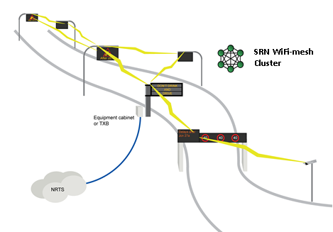
Figure 6 Diagram of a wifi-mesh network suitable for highway data transmission
(Figure courtesy of Barry Moore)
Bluetooth technology also supports data exchange over short distances. It uses short-wavelength ultra-high frequency (UHF) radio waves. Bluetooth technologies are used in many different applications such as smart phones, headsets, tablets and laptop computers. Recently, there has been increased interest in building on the presence, on-board vehicles, of Bluetooth devices in “discoverable” modes, to track and monitor traffic. These applications use roadside Bluetooth detectors to discover Bluetooth devices on-board the vehicles and detect their unique identifier. By tracking the same identifier through different location points, important traffic parameters can be determined such as travel time, speed, vehicle origin and destination.
Another group of communications technologies widely used in ITS is dedicated short-range communications (DSRC). DSRC was developed specifically for vehicular communications and is likely to witness a dramatic increase in use with the introduction of Connected Vehicle technologies. The technologies are used in a number of ITS applications including:
In the USA, DSRC generally refers to communications on a dedicated 5.9GHz frequency band reserved specifically for Wireless Access in Vehicular Environment (WAVE) protocols – defined in the IEEE 1609 standard and its subsidiary parts. These protocols are based on the widely-used IEEE 802.11 standard for Wi-Fi wireless networking.
Several DSRC technologies are used in transportation. These include:
Passive tags do not have an internal power supply. Instead, they use the very small electrical current induced in the antenna by the incoming radio frequency signal, to transmit a response. For this reason, the antenna has to be designed not only to collect power from the incoming signal, but also to transmit the outbound backscatter signal. The main advantage of passive microwave tags is that they can be quite small and have an unlimited life. Passive microwave was used in ITS for early types of electronic toll collection systems. Innovations in their use continue.
Active tags have their own internal power source which can generate the outgoing signal. Compared to passive tags, they may have a longer range and can store additional information sent by the transceiver. Active microwave is employed in many electronic toll collection systems. More expensive on-board units have batteries which need replacing.
Infra-red DSRC uses infra-red technology, as opposed to radio spectrum or microwave, for short-range communications. Infra-red DSRC can be used in ITS where it is difficult to secure a frequency spectrum license. The technology is also appropriate when the weather is generally rainy – but not foggy. Infra-red DSRC is less susceptible to security intercepts.
Bluetooth is a wireless technology designed to allow data exchange over short distances (a maximum of about 10 meters). Most cell phones on the market today have Bluetooth technology. They also have Wi-Fi wireless technology, which uses radio waves for connections for distances to a Wi-Fi base station of up to 90 meters. In recent years, several automotive manufacturers have been embedding Bluetooth technology into their vehicles to allow drivers to connect their phones or music devices to in-vehicle audio systems.
When activated, Bluetooth and Wi-Fi transceivers continuously broadcast “discovery” messages to allow other devices to find and connect with them. The discovery messages include a unique identifier that can be used for vehicle detection and tracking. Essentially, all that is needed is a Bluetooth or Wi-Fi sensor installed close to the roadway. These sensors record the time at which a a vehicle equipped with an on-board Bluetooth or Wi-Fi device drives past them. By utilising the unique identifiers recorded at successive monitoring points, information on travel times along a road segment – or the pattern of Origin-Destination flows through a network – can be derived.
The use of Bluetooth or Wi-Fi is ideal for crowd sourcing but the results have to be calibrated as:
not all vehicles report an identifier – since some will not be equipped with the technology or the equipment may be turned off – leading, in both cases, to no count being registered
or a single vehicle may have several active devices – leading to multiple counts.
When using this vehicle sampling technique a key challenge is to ensure that a sufficiently high proportion of vehicles are equipped with Bluetooth and Wi-Fi devices. In urban areas, this may not be a major concern, but in other regions low market penetration may limit the application of these detection technologies.
Communications over a wide area are often required in Network Operations – particularly in rural areas where the options for voice and data communications and the transmission of CCTV images are more limited.
WiMax stands for Worldwide Interoperability for Microwave Access. WiMax is designed to provide much higher bandwidth, compared to Wi-Fi, and at a much extended range. Recent years have seen increased interest from the ITS industry in integrating WiMax and Wi-Fi as an alternative communications medium to wired communications.
Under ideal conditions, WiMax could have a range of more than 40 kilometres, and offer speeds of up to 70 Mbits/seconds. It implements the IEEE 802.16 Standard, with newer standards designed for speeds of up to 1 Gbits/second. A typical WiMax network would consist of a base station connected to several client radios (Customer Premise Equipment or CPE).
Cellular networks were established primarily for voice communications, but there is steadily growing increased interest in their use for data communications as well. Two voice communication cellular technologies have evolved in this way:
Global System for Mobiles (GSM)
Code Division Multiple Access (CDMA)
They differ in the way they transfer data. GSM divides the frequency band into multiple channels for use by different users. CDMA digitises calls and unpacks them at the back end. Both GSM and CDMA have been refined and enhanced over the years to allow for increased speed. For example GPRS (for packet data communications) uses the GSM cellular network at speeds suitable for transmitting commands to VMS and car park counters.
The latest cellular data technology is Long Term Evolution (LTE) (also known as 4G LTE). Unlike GSM and CDMA, LTE is designed primarily for data communications, with voice as an override. It offers high bandwidth, low latency, and supports full data rates while travelling at high speeds (a feature which is important in the ITS environment with fast-moving vehicles). Cellular data communications can be used in ITS where wireline communications are not available or are cost-prohibitive.
Digital Radio Data (DRT) refers to the practice of transmitting digitised and compressed data over FM radio. This allows small amounts of digital information to be embedded in conventional FM radio broadcasts. A good example of a DRT application in ITS is the Radio Data System-Traffic Message Channel (RDS-TMC), where digitally encoded traffic information is made available for in-vehicle navigation devices. RDS-TMC is an early form of digital data transmission. It was developed in Europe to exploit the Radio Data System used by some broadcasting authorities. Travel information is transmitted digitally over FM radio frequencies – and a decoder, built into the car radio or navigation device, interprets the digital code for text or graphic display.
Spread spectrum radio is a radio network that has a “line-of-sight” requirement (unobstructed line of path between a subject and an object). In this network, one radio serves as the master and the other as slave. An example of the use of spread spectrum radio in ITS is the connection between a set of traffic controllers at signalised intersections and the Traffic Management Centre (TMC) needed for monitoring and signal timing purposes.
In some cases, it might not be possible to directly link the two radios because of distance or interference – in which case another radio (called a repeater) would need to be installed in-between the two radios. These networks are most commonly used to allow a number of traffic controllers to communicate with one another, or to communicate with a traffic operations centre. They can broadcast over the unlicensed frequencies of 900MHz, 2.4 GHz and 5.8 GHz. The 5.8 GHz frequency provides the highest bandwidth at about 54 Mbits/second, but is very susceptible to line-of-sight problems.
Whilst theoretically, spread spectrum radio can provide a communication range of up to 60 miles, in practice the range is much shorter because of line of sight attenuation or obstructions.
A number of traffic control strategies can be implemented in Road Network Operations in order to improve traffic flow, prevent congestion and enhance throughput. ITS software – supported by a wealth of real-time data enabling accurate estimates to be made of the status of the road network – is used to develop optimal management and control strategies that support network policy objectives. These will vary from one location to another, but commonly include maximising traffic throughput, minimising delays and congestion, maintaining road safety for all road-users – including safe crossings for pedestrians and cyclists – environmental targets (to reduce noise levels and/or air pollution) and bus/tram signal priority for some locations.
Control methods include:
Urban Traffic Control (UTC), with:
Motorway control systems, including:
Field controllers are needed to implement these strategies. They are the “brains” of the local system, and provide the means for accessing, monitoring and controlling field equipment (such as a ramp meter, a traffic signal, or a vehicle detector).
Computer software is needed to provide these functions. Some of the functions that an ITS system software may be required to provide include urban traffic control, traffic control on arterial roads and motorway control systems.
Urban Traffic Control refers to a package of technologies aimed at managing and controlling traffic flowing over urban networks – to minimise delay, maximise efficiency, improve safety and reduce emissions and fuel consumption. A large part of urban traffic control involves software to optimising signal plans at intersections to achieve these objectives. This requires extensive sensor networks to collect real-time traffic information – for example, loop detectors, closed-circuit TV cameras and video image processing, or non-intrusive traffic detectors. Based on the collected information, intelligent algorithms aim to optimise the signal plans. Different levels of control and sophistication are seen in urban traffic control systems (See Urban Traffic Control).
Several types of field controllers are available which respond to traffic demands to facilitate turning movements and allow time for cross-traffic. In the USA the Type 170 Controller was developed in the early 1970s by the California Department of Transportation. Its successor – Type 2070 – was introduced in 1992. More recent examples are the NEMA signal controllers and the Advanced Traffic Controller (ATC – 2005) – the most advanced controller in the USA.
Traffic signal controllers work on the basis of a timing cycle that is broken into “phases” – the order in which each traffic stream is given green time, whilst other traffic is held at red. A simple cross-road intersection may have just two phases: North/South, and East/West. A busy four-way intersection, with large volumes of turning traffic, might have up to eight phases – one phase for each of the four traffic directions and a phase for each of the turning movements.
In the United Kingdom, a relatively new controller called Microprocessor Optimised Vehicle Actuation (MOVA) was developed to overcome some of the limitations associated with traditional Vehicle Actuation (VA) control. A unique feature of MOVA is that it has two modes of operation – one for congested traffic conditions and one for uncongested or free-flow conditions. For free-flow conditions, the aim of MOVA is to deal with any queues that have accumulated during the red phase. An algorithm assesses the traffic loads from different intersection approaches and determines whether extending the green time is beneficial. If it is, the green phase is extended to let traffic through. This continues until the controller moves to a different phase. During congestion, MOVA’s operational objective changes to maximise the capacity or throughput for the intersection as a whole.
Motorway control systems focus on better management of motorway segments to enhance capacity and increase throughput. Over the years, several Decision Support Systems (DSS) have been proposed and developed to help this process. These DSS can provide recommendations to traffic operators on possible traffic control strategies – such as dynamic route guidance, ramp metering, changeable speed limits and optimal signal timing.
Automated motorway control systems (sometimes referred to as Active Traffic Management or ATM systems), use different concepts to achieve their goal – such as speed harmonisation, temporary shoulder usage, dynamic routing and signing, junction control and ramp metering (See Highway Traffic).
Active Traffic Management has been widely implemented in Europe, and is becoming a tool for managing congestion (both recurring and non-recurring), in the USA as well. The main technological components of ATM are similar to the UTC systems and include extensive sensing and monitoring systems, communications, controllers, and intelligent algorithms.
The benefits of Active Traffic Management systems include:
Urban Traffic Control (UTC) systems require traffic signals, signal controllers, ramp meters and dynamic message signs (Variable Message Signs – VMS) to control traffic. They also require:
Different approaches and measures are used for real-time traffic management and control in urban areas.
Computer signal control systems first appeared in the 1960s when computers were first used to coordinate the traffic signal controllers for a group of intersections – but without the benefit of today’s “feedback” of information from the field detectors to the computers. In this type of system (known as open-loop control) the traffic plans that are implemented are not responsive to actual traffic demand. Instead, plans are developed “off-line” using data from historical traffic counts – and implemented according to time-of-the-day and the day of the week.
This system is quite basic, but it still offers several advantages including:
The next level of sophistication is signal control systems where information from field traffic detectors is fed-back to the central computer. The computer uses the information on current traffic conditions to select the signal plan to be implemented (closed loop control). Plan selection is made according to one of the following methods.
Here, the system has access to a database (library) that stores a large number of different traffic patterns along with the “optimal” signal plans (developed off-line) for each traffic pattern. Based upon information received from the traffic detectors, the computer matches the observed traffic pattern to patterns stored in the library, to identify the most similar pattern. The “optimal” plan associated with the identified pattern is then implemented. This type of adaptive traffic control system is often referred to as a First Generation system. Its distinguishing feature is that the plans, while responsive to traffic conditions, are still developed off-line. First Generation systems work on the basis of current traffic data and do not generally have traffic prediction capabilities.
In this method, the “optimal” signal plan is computed and implemented in real-time. The optimal signal timings are computed in real-time using current data on traffic conditions obtained from detector information. This requires sufficient computational power to make the necessary computations on-line. It also needs enough data from the vehicle detectors to make the calculations. The systems that develop plans on-line are classified as either Second-Generation or Third-Generation systems. They typically have a much shorter plan update frequency compared to First-Generation systems, typically every 5 minutes for Second-Generation systems, and from 3 to 5 minutes for Third-Generation systems. In addition, some Third-Generation systems use forecasts of traffic conditions obtained from feeding the detector information into a short-term traffic-forecasting algorithm.
There are a number of examples of adaptive traffic control systems in use around the world. Amongst the most widely accepted algorithms are SCOOT, SCATS and RHODES.
SCOOT (Split, Cycle, Offset Optimisation Technique) is an adaptive traffic control system developed by the United Kingdom’s Transport Research Laboratory (TRL) in the early 1980s. SCOOT operates by attempting to minimise a performance index (PI) – typically, the sum of the average queue length and the number of stops across the controlled network. In order to do this, SCOOT modifies the length of the cycle, the amount of green time given to each signal phase (known as the time “splits”), and the offset time for each set of signals (the time difference between the cycle start times at adjacent signals). SCOOT computes these calculations in real-time in response to the information provided by vehicle detectors.
The operation of SCOOT is based upon Cyclic Flow Profiles (CFP). These are presented as histograms (graphical representations of user-specified ranges) that show the variation in traffic-flow over a cycle – which is measured by loops and detectors that are placed midblock on every significant link in the network. Using the CFPs, the offset optimiser calculates the queues at the stop-line. The optimal splits and cycle length are then computed.
Several additional features have been added to SCOOT to improve its effectiveness and flexibility, including the ability to:
The Sydney Co-ordinated Adaptive Traffic System (SCATS) was developed in the late 1970s by the Roads and Traffic Authority of New South Wales in Australia. For operation, SCATS only requires stop-line traffic detection, not the midblock traffic detection that is necessary for SCOOT. This simplifies installation since the majority of existing signal systems are equipped with sensors only at stop-lines. SCATS is a distributed intelligence, hierarchical system that optimises cycle length, phase intervals (splits), and offsets in response to detected volumes. For control, the network of signals is divided into a large number of smaller subsystems, each ranging from one to ten intersections. The subsystems run individually unless traffic conditions require the “marriage” – or the integration – of the individual subsystems.
Since 1991, the University of Arizona has been developing a real-time adaptive control system called RHODES, which stands for Real-time Hierarchical Distributed Effective System. RHODES is designed to take advantage of the natural stochastic (random) variations in traffic flow, to improve performance – a feature which is missing from systems such as SCOOT and SCATS.
The RHODES system consists of a three-level hierarchy that decomposes the traffic control problem into three components: network loading, network flow control and intersection control:
Level 3 is concerned with intersection control – determining the optimal time to change traffic signals for the next phase sequence and whether the current phase should be shortened or extended. The time frame for control level 3 is typically in the order of seconds and minutes.
Where there alternative routes available the problem of optimising traffic on the network can be tackled mathematically. For dynamic route guidance (DRG) the “objective function” (an equation expressing the operational function that needs to be maximised or minimised) – is the measure of the highway network’s performance that needs to be optimised. For example the objective might be to minimise the total travel time for all vehicles. The decision variables are the proportions of traffic that splits at each diversion point – to optimise network performance. The traffic-splits define how traffic should be distributed. The aim is to model traffic flow in the region and ensure that it is maintained at the nodes and along the links of the network, without congestion setting in. ITS software can then be used to solve the problem of optimising the objective function and recommending a routing strategy that will vary in real-time according to traffic conditions. Routing advice will be given in traffic broadcasts and on VMS, or with in-vehicle route guidance for those vehicles that are equipped.
Public transport priority (known as Transit Signal Priority or TSP in the USA) is a measure aimed at reducing delay for public transport vehicles (buses, trams, taxis) at signalised intersections by giving their movements preferential treatment. The methods for doing this can be divided into passive and active strategies. The basic difference is whether specialised sensors and detectors are used to detect approaching public transport vehicles. Without supporting technologies to specifically identify these type of vehicles, passive TSP technology simply improves conditions for all vehicles along a public transport corridor.
Active technologies detect an approaching bus or tram (this is typically accomplished by having a transmitter on the vehicle that communicates with a receiver or detector on the roadside signal controller). Different algorithms or strategies are available for active bus priority. Amongst the most common are:
Green Extension: this extends the green time if a bus or tram is detected, to allow the priority vehicle to pass – up to a certain pre-determined limit. This strategy only benefits a small portion of vehicles, but the reduction in delay for beneficiaries is significant (equal to the length of the whole red interval)
Early Green: shortens the green time for conflicting phases, by a pre-defined amount of time – for example when the bus arrives whilst the traffic light is in its red phase. Early green benefits a large percentage of buses, but the saving per vehicle is not as large as for Green Extension
Phase Rotation: under this strategy, the sequence of green time for different manoeuvres at the intersection is changed so that the priority vehicle is not held up. One common modification – that allows the vehicle to cross the opposing traffic stream – involves swapping a dedicated turn signal at the start of the cycle (the “leading” phase) to the end of the cycle (the “lagging” phase).
Actuated Transit Phase(s): involves establishing transit phases, which are only active when a bus/tram is present. In this case, a special transit signal face would display, for example, a letter “B” for Bus or “T” for Tram.
Phase Insertion: this allows the same phase to appear more than once during the same cycle in order to serve the transit vehicle.
An important function that ITS software can provide for Road Network Operations is the ability to detect incidents and abnormal conditions from automatic analysis of the real-time traffic surveillance data. The development of Automatic Incident Detection (AID) algorithms began in the 1970s, and since then many algorithms have been developed. They have had mixed success, primarily because of their relatively high false-alarm rates (measured as the ratio of the number of false detections and the total number of observations).
AID algorithms can be broadly divided into four groups based on the principle behind the algorithm’s operation. These groups are:
These are among the most commonly-used AID algorithms. They are based on the premise that the occurrence of an incident results in an increase in the density of traffic upstream and a decrease in traffic density downstream. The California Algorithm is one of the earliest comparative-type AID algorithms to be developed – and is often used for comparisons and bench-marking. Since the original California algorithm was first developed refinements have been made to its performance. At least 10 new algorithms have been produced, of which algorithms 7 and 8 are the most successful. The TSC 7 algorithm represents an attempt to reduce the false-alarm rate of the original algorithm. The TSC 8 algorithm test repeatedly for congestion effects upstream of an likely incident and monitors other traffic characteristics.
Catastrophe Theory derives its name from sudden changes that take place in one variable that is being monitored – whilst related variables, also being monitored, show smooth and continuous changes. For incident detection, catastrophe theory algorithms monitor the three fundamental variables of traffic flow – namely speed, flow and lane occupancy (density). When the algorithm detects a drastic drop in speed, without an immediate corresponding change in occupancy and flow, this is an indication that an incident has probably occurred. The McMaster algorithm developed at McMaster University in Canada is a good example of an algorithm based on this concept.
Statistical and time series methods are used to forecast future traffic states or conditions. By comparing real-time observed traffic data with data forecasts, unexpected changes are classified as incidents. An example of these algorithms is the Auto-Regressive Integrated Moving-Average (ARIMA) time series algorithm. ARIMA is used to provide short-term forecasts of traffic occupancies based upon observed data from three previous time intervals. The algorithm also computes the 95% confidence interval. If observations fall outside the 95% range as predicted by the model, an incident is assumed to have occurred.
Several Artificial Intelligence (AI) concepts have been applied to problems in transport engineering and planning. Automatic incident detection is one application. Detecting incidents is a good example of a group of problems known as pattern recognition or classification problems – for which AI theories are quite effective in solving. Amongst the AI concepts most often applied to the problem of incident detection are Artificial Neural Networks (ANNs). These use complex algorithms and multiple computer processors to recognise patterns and connections in the input data.
Over the last few years automotive manufacturers have been introducing sophisticated vehicle control technologies to improve safety, fuel efficiency and comfort level of drivers, amongst other things. These new technologies are sometimes called Advanced Driver Assistance Systems (ADAS). These systems use sensor technology, including automotive radar, that has been developed specifically for use in motor vehicles (See Warning and Control). They have a positive effect on safety and traffic management by helping drivers to maintain a safe speed and distance, keep within the running lane and avoid unsafe overtaking manoeuvres. Benefits can be further magnified if individual vehicles communicate continuously with each other or with the road infrastructure – so-called ‘connected’ vehicles (See Connected Vehicles).
Examples of longitudinal vehicle control are Adaptive Cruise Control (ACC) and Co-operative Adaptive Cruise Control (CACC). ACC is designed so that a car automatically maintains a safe distance from the vehicle ahead in terms of distance or time headway, as programmed by the driver. The driver specifies the maximum speed (as with normal cruise control) and the follow distance. An on-board radar sensor locks onto the vehicle ahead and the vehicle control system maintains the specified distance. ACC is often accompanied with a forward collision warning system that alerts the driver in case of an obstruction hazard ahead. It may even start to apply the brakes if the driver fails to do so.
Research is taking place that combines ACC with inter-communications between vehicles.. With communications added, ACC becomes Co-operative Adaptive Cruise Control (CACC). Communications allow the front vehicle’s rate of acceleration or deceleration to be communicated in real-time to the vehicle following (several times per second). The real advantage of CACC is to reduce delay in the response of the vehicle behind.
Some high-end new cars on the market now include lane departure warning systems and lane-keeping support systems. These keep track of the vehicle’s position relative to the running lane. They use a suite of sensors such as video sensors mounted behind the windshield, laser sensors on the front of the vehicle, and/or infrared sensors under the vehicle. Warning systems only sound if the vehicle starts to deviate from the lane, whereas lane-keeping support systems may take remedial action to return the vehicle to a safe position within the lane.
By combining technologies, the next evolution in vehicle control systems is autonomous or self-driving vehicles.
The US National Highway Traffic Safety Administration (NHTSA) has defined five levels of automation to describe systems with varying degrees of autonomyin the following way:
The Google car is an example of what is in development and on trial in California. youtube (See Video)
Digital mobile telecommunications are having a profound effect on the operating environment for ITS by enabling Vehicle-to-Vehicle (V2V) and Vehicle-to-Infrastructure (V2I) communications. The combination of the two is sometimes referred to as V2X communications – meaning networked wireless communications between vehicles, the infrastructure (roadside units and traffic control centres) and passengers’ personal communications devices. A vehicle can broadcast data describing its position, movements and manoeuvres – and share this with other vehicles to prevent collisions, and with the infrastructure to optimise traffic control.
The ability to send and receive this data enables intelligent vehicle systems to integrate information from navigation systems with data from on-board sensors and information received from the infrastructure. This provides vehicle systems with an awareness of its immediate surroundings, including areas which may not be visible to the driver – which can be used to assist the driver to drive more safely. If the vehicle systems anticipate an accident they can, as a minimum, prepare safety systems and, perhaps, intervene to prevent an accident.
The technologies needed to implement a connected and Cooperative Vehicles (CV) environment fall into four separate components:
The OBE are:
Some of the vehicle-based information can be obtained from GPS or other similar sensors (for example location, speed, and direction), whereas other information (for example acceleration, instantaneous fuel consumption, anti-lock brakes activation, wiper status) may be obtained from vehicle engine scanning tools and other systems monitoring the vehicle’s different subsystems.
Connected vehicles are instrumented with a wide range of sensor technologies to enable applications aimed at improving safety and efficiency – including:
Roadside units and equipment are infrastructure systems that communicate with vehicles and collect data from the vehicle. Roadside equipment can support infrastructure-based applications – or applications involving co-operation between vehicles and the infrastructure (such as intersection collision avoidance systems, and eco-signals which inform approaching vehicles about the remaining green-light time to enable drivers to adjust their speed). Roadside equipment also supports remote applications by communicating information collected from the vehicles to a central location for processing. They also may help support the security and integrity of cooperative vehicle systems.
The communications network is the infrastructure needed to provide connectivity between vehicles (V2V), between vehicles and the infrastructure (V2I), and between roadside equipment and other parts of the system (V2X). Wireless communications are required for V2V and V2I communications, whereas roadside equipment may use wireless or wired networks.
The Connected Vehicles Initiative – USA
In the USA, the focus has been on using Dedicated Short-Range Communications (DSRC) for cooperative vehicle systems. Similar to Wi-Fi, DSRC is an open-source protocol for wireless communication. However, the big difference is that DSRC is intended for highly secure and high-speed communications – features that are critical for safety applications. DSRC has the following beneficial features:
low latency (as low as 0.02 seconds)
robustness in the face of interference
dedicated bandwidth protection (depending on bandwidth allocations in the country concerned)
In the USA, in 2004, the Federal Communications Commission, dedicated 75 MHz of bandwidth at 5.9 GHz, to be used for the Cooperative Vehicles initiative.
The rapid progress in mobile telecommunications means that the connected vehicle is no longer a research concept but a reality. Applications fall into four different, but not necessarily separate, categories:
connected vehicle safety applications – examples include driver advisories, driver warnings, and vehicle and/or infrastructure controls (See Driver Support);
connected vehicle mobility applications that use real-time data. The data are transmitted to vehicles wirelessly and are used by information service providers to broadcast current traffic conditions for satellite navigation systems. Data obtained from connected vehicles also has value for network management activities and for traffic engineers to optimise the performance of the transport system (See Probe Vehicle Measurements);
connected vehicle environmental applications that use real-time data from vehicles to support the development, operation, and use of "green" transport applications (See Smart Network Operations);
commercial applications that enhance the way business is conducted and open up new market areas – such as location-based added value services (See Location Based Services).
One of the most successful applications of ITS is electronic payment (See Electronic Payment). Non-stop electronic payment supports payment of vehicle tolls on the go. Smart travel cards support fare payment for combined transport services (bus, rail, metro, river transport, parking).
Electronic payment applications integrate technologies for communications, data processing, data storage and microcomputing. The process comprises “front end” and “back-end” activities.
“Front-end” activities are those seen by the user. The most common “front-end” hardware technologies are smart cards, transponders (tags, such as the EZ-pass widely used for electronic toll collection in the USA), and – increasingly – smart phones.
“Back-end” activities are those related to payment processing, account maintenance, customer service and reporting.
Electronic payment is widely used for collecting road tolls whilst the vehicle is in motion. The main components of the system are the transponder (also known as toll tags), the tag reader and the computer system for data processing. Most transponders use Radio Frequency Identification technology (RFID). There are two types of transponders: active and passive. Active transponders carry their own power supply (batteries), whereas passive transponders are powered by the radio frequency (RF) pulse they receive from the reader. Passive transponders are cheaper to buy but they have a shorter communication range and transit less data. Newer models of transponders are designed to allow for integration with smart cards (using built-in slots).
Electronic fare payment systems are commonplace and offer a number of advantages over traditional payment methods:
There are two basic types of electronic fare payment systems: closed systems and open systems.
Closed systems are limited to one main purpose (such as paying transport fares) with perhaps a few additional add-on applications such as paying parking fees. The payment value stored on the card cannot be used on anything other than a pre-agreed and pre-defined activities.
Open systems can be used to pay for other purchases in addition to transport. An example is a credit or bank debit card which can be used with multiple merchants, but fare payment is not an attractive application for credit cards companies because the transactions are high volume and low-value.
A smart card is a card which looks like a credit card in size and shape, but has an embedded microprocessor – in effect, replacing the magnetic strip on a credit card.
Smart cards facilitate the collection and management of payments using electronic media instead of cash or paper transfers. The system consists of two main components – a card and a card reader. Cards can be of the magnetic-stripe type where the reader does most of the data processing – or they can be equipped with a microprocessor, in which case, data processing can take place on the card itself (this is the more popular option).
Smart cards can provide identification, authentication, data storage and application processing. Their use for electronic payments offers the traveller and the transport company/agency several benefits – including time savings, a more convenient payment method, the ability to implement more flexible but complex ticket pricing strategies, lower administrative costs, and better data for future planning. They also allow integrated ticketing strategies so the traveller can use a single card to pay for their transport – whether it be by bus, train, underground/metro/subway or ferries.
Smart cards can be of two types: contact smart cards and contactless smart cards:
A number of other technologies have been adapted for electronic payment – including DSRC/GNSS-based systems and automatic number plate recognition systems.
These systems have been used for or urban tolling or a congestion charge, based on Dedicated Short Range Communication (DSRC) technologies. The standard microwave frequency of 5.8 GHz is used for communication between roadside transponders or antennas and in-vehicle devices.
GNSS-based systems use Global Navigation Satellite System (GNSS) sensors inside the vehicles. This allows a wide range of pricing strategies to be implemented including strategies based on distances travelled. GNSS sensors record time and vehicle position data, which are then processed into trip information and matched against an established pricing scheme. The processing of the data can be performed at a central location or on-board the vehicle itself. The first successful demonstration of GNSS-based pricing systems took place in Germany on the A555 motorway between Bonn and Cologne.
With the wide-spread adoption of smart phones, a number of apps have been developed where the smart phone can act as a payment device. An example is the “paybyphone” app to pay for tolls and parking (See http://paybyphone.com/how-it-works/).