
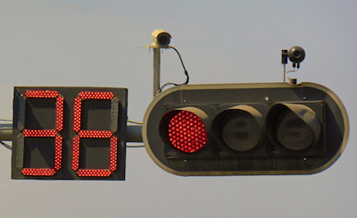
Cairo, Egypt – Countdown traffic signals
Increase of road traffic is closely related to a region’s economic prosperity. Increased economic activity stimulates transport demand for individuals, goods and freight, which puts pressure on the road network. However, the problems of traffic jams have become a serious social issue throughout the world. It is simply impossible to accommodate all vehicular traffic demand through the construction of new roads. Moreover, the construction and improvement of roads themselves invite further economic development, leading to more vehicles on the network, which may exceed the added capacity and worsen the situation. Increased numbers of vehicles also have negative side effects other than congestion. Therefore, network operations have to include ways to manage and control traffic on the network, rather than forever playing catch-up with traffic demand.
The policy challenge is to determine whether to intervene with control measures and how best to achieve the desired results. Local policy objectives vary from achieving the maximum unimpeded traffic flow without compromise, to one of severe traffic calming with priority to pedestrians, cyclists, animal transport and other classes of slow-moving traffic. However, intervention is more widely used to help achieve policy objectives.
Traffic Management refers to the combination of measures that serve to preserve traffic capacity and improve the security, safety and reliability of the overall road transport system. These measures make use of ITS systems, services and projects in day-to-day operations that impact on road network performance.
Central to this approach is the development and integration of a set of traffic management measures appropriate to the local and regional requirements – and to achieve this through a planning process that makes use of systems engineering, standardisation and documentation, and performance management.
The emergence of ITS in the field of traffic control has enabled a number of new concepts to be applied in the framework of innovative operational systems. Examples include bus and tram priority, and pollution monitoring. These features are starting to be deployed amongst established traffic management systems.
When traffic control systems have been found to reach their limits and where adding capacity or new building of road infrastructure is not feasible, further measures may become necessary. These may include restrictions on the free use of individual vehicles through Electronic Road Pricing (ERP) or a Congestion Charge. (See Congestion Charge)
Some examples of traffic management measures that may feature as part of a network operating strategy are:
Some years ago, a study in the USA set out to quantify the leading causes of traffic congestion. The results, averaged for all roadways, are shown in the Figure below. A large proportion is attributable to road bottlenecks and poor signal timing (40% and 5% of all congestion in this example). This congestion is repeated on a daily or weekly basis and is referred to as recurring congestion.
Although the data shown in the figure below is particular to the USA, the high incidence of bottlenecks points to issues of network management and infrastructure inadequacies. This is the case particularly at road intersections and junctions, and can be seen across the world. Extensive traffic management measures are deployed to address these problems. The proportions in the figure are composite estimates derived from many past and ongoing congestion research studies. They can be considered as enduring proportions as they continue to feature in the current equivalent (2015) FHWA publication
")
Sources of Congestion (USA 2005)
As the figure shows, the leading cause of non-recurring congestion is traffic incidents. Nearly all of non-recurring congestion can be mitigated by better operational strategies. Even with bad weather, ITS can help with mitigation. Dealing with more severe emergencies usually presents orders of magnitude in challenges – but again, better operational planning, preparation and response can help mitigate many of their impacts.
Programmes that seek to minimise non-recurring congestion include the coordination of regional road network operations, traffic incident and emergency management, work zone management, road weather management and roadway ITS maintenance operations. Other approaches to congestion mitigation include traffic control and demand management. (See Traffic Control and Demand Management)
Specific guidance on a number of traffic management services have been developed by European road authorities and operators as part of the European “EasyWay” project. The EasyWay ITS deployment guidelines are available for download at http://dg.easyway-its.eu/DGs2012
The Chartered Institution of Highways & Transportation (UK) Network Management Notes cover a number of traffic management topics and are available for download at http://www.ciht.org.uk/en/knowledge/standards-advice/network-management-notes/index.cfm
The publication "Green and ITS" has a useful chapter on Traffic Management. (See Green and ITS)
ITS and other measures can be applied to control traffic to deal with recurring congestion across urban areas and on regional networks of motorways, freeways, expressways and other arterial roads. The general objective of these measures is to make better use of available capacity through traffic flow improvement strategies, or in many cases by adding extra traffic capacity.
Systems to manage traffic are diverse and can be considered at two levels:
Traffic Control Centres (TCCs) responsible for regional networks have the job of coordinating traffic management on the most heavily trafficked routes. (See Traffic Control Centres) Traffic management at this tactical level involves the implementation of localised schemes, such as ramp metering, automatic incident detection and use of CCTV, supported by the widespread use of VMS. The control systems themselves can be grouped into four categories:
Aside from budgetary considerations, the choice of measures depends largely on the local operating context which covers a spectrum of different operating environments – from high-speed multiple-lane motorways that experience recurring congestion to all-purpose rural 2-lane roads with only seasonal traffic problems.
For a particular section of road the operating environment is determined by a combination of three factors:
The European EasyWay project has developed a classification system for operating environments on the Trans-European Road Network that reflects the level of service expected by road-users, the frequency of recurring congestion and traffic incidents and the feasibility of possible ITS solutions to deal with these problems. It can be used to select the parts of the road network where improvement using traffic management would be beneficial – and for prioritising where to implement different measures. For core (network-wide) ITS services the operating environment classification can be used to prioritise implementation if this has to be done in phases.
Further Information
EasyWay ITS Deployment Guideline ICT-DG01 EasyWay Operating Environments Available for download at: http://dg.easyway-its.eu/DGs2012
Traffic signal control on all-purpose single and dual carriageway arterial roads is frequently used at isolated intersections, often using a demand-responsive control strategy. The installation of traffic signals on any high-speed road demands great attention to traffic safety. Adopting motorway style control and signalling on all-purpose arterial roads is primarily an investment issue: when the need is perceived to be significant the investment budget will be found and the supply base will respond.
As traffic volumes continue to increase, the need to consider areas of the regional network that require special treatment in terms of traffic management will also increase. Sometimes the only tactic during a traffic incident is to keep traffic queuing on the highway to avoid causing much wider disruption. One example is where regional inter-urban routes enter a conurbation, requiring the motorway control systems to be closely integrated with the urban traffic control system. (See Integrated Strategies)
Strategic traffic management is concerned with advising drivers of major incidents and problems so they can adapt journey plans accordingly. Strategic measures are of particular benefit to long-distance traffic and make full use of traveller services – in particular dynamic (traffic responsive) journey planning and en-route information. (See Traveller Services) The network controller’s objective is to balance the flows of traffic on the different routes to the same destination area. A more even distribution of traffic helps reduce congestion and, in the event of a major incident, the ability to respond quickly by diverting traffic away from the affected area. Even a small reduction in demand resulting from advance information can have a dramatic effect on recovery times if it can prevent saturation and flow breakdown.
Advances in technology have made the concept of regional and strategic traffic control more realistic. Strategic traffic management systems are installed to monitor traffic across a regional network of strategic roads where alternative routes exist. These measures provide warnings of serious disruption to traffic with advice and directions on the recommended routes for long-distance traffic.
Network traffic assignment models (such as Motorway CONTRAM in the UK) are sometimes used to decide when to initiate a strategic diversion route. Traffic and travel information systems (VMS, advisory systems and other en-route driver information) are used to advise drivers when there is congestion and delays. (See En-Route Information)
These regional control systems require the interchange of information between local tactical control centres and the strategic regional centres. In Europe several system suppliers offer modular systems that combine urban traffic control and highway traffic functionality to enable local and regional network control.
The trend towards more integrated traffic management will drive greater functional integration of traffic monitoring, traffic information systems and traffic control. Provided there is sufficient spare capacity on the regional network to allow effective strategic re-routeing, network control should significantly reduce delays, increase safety and reduce pollution.
Traffic control covers all measures aimed at distributing and controlling road traffic flows in time and space in order to avoid the onset of incidents or to reduce their impacts. Traffic control is carried out by network operators and controllers with reference to predetermined traffic management policies and plans. In most countries it is an activity done in coordination with the authorities in charge of traffic policing, often under their direct control. (See Traffic Management Plans)
It is possible to distinguish between:
Indirect control measures can be characterised as either preventive action or actions that are remedial or corrective. Indirect control methods are supported by travel information systems. (See Traveller Services)
Preventative action aims to warn drivers of current and forecast problems so they can make adjustments to their travel plans. It may include warning drivers of anticipated problems so that they can change their travel times, choose different routes or abandon their trip. This requires:
Data being generated by ITS field devices and floating vehicles (probes) are valuable resources that provide a foundation for the use of simulation models that can predict congestion and/or journey times. This enables logistics system managers and TCC operators to take action to avoid the onset of congestion—either by diversion or with advice on trip changes.
Remedial or corrective action is designed to limit the extent or impact of delays and congestion that occurs regularly on strategic routes, using measures to limit access and –at a regional level – to divert traffic onto less congested routes. Diversionary routes need to be planned in cooperation with the road authorities and operators of the alternative routes. Often, an alternative high-capacity route will not be available and other options would only be suitable for light traffic – not trucks and heavy goods vehicles. Some road authorities operate seasonal “holiday routes”. Others will only divert traffic when there is a road closure or an emergency (except at ramp meters, where the diversion is indirect).
Remedial action requires:
Closed-Circuit Television (CCTV) coverage of regular “hot spots” for accidents or congestion on the network are an essential part of modern Road Network Operations. Operators in the Traffic Control Centres (TCCs) will scan the CCTV images looking for signs of traffic disruption, such as a smoking vehicle that might break down, debris on the roadway, dangerous or excessive vehicular manoeuvres, or anything that might lead to a traffic incident and congestion. Ongoing developments using image recognition technique are enabling a degree of automation of incident detection. (See CCTV)
Many TCCs do not have sufficient operators to focus on camera scans, even using “camera tours” or “video tours” to monitor a sequence of cameras. More commonly they use system performance measures to alert operators to an incident.
The image below shows an innovative approach used by Florida DOT’s District 4’s TCC in Broward County (USA), in which the entire section of Interstates 95 and 75 can be monitored in its control area on wall projections. It displays the speed profile (average speed) of the traffic on the two interstates, so that operators can quickly identify hot spots. Taking proactive action before a suspected incident occurs is much like preventive maintenance – namely, “Fix the problem before it gets worse.”
")
System Status Wall Display (Photo courtesy of Florida DOT District 4, used with permission.)
Variable Message Signs are also referred to as Dynamic Message Signs and Changeable Message Signs. A Dynamic Message Sign (DMS) refers to any sign or graphics board where the message (text or pictogram) conveyed to the viewer can change. A DMS may be either a Variable Message Sign (VMS) or Changeable Message Signs (CMS) where:
A Portable Dynamic Message Sign is referred to as a PDMS
Roadside Dynamic Message Signs are the most common way of implementing network control strategies and communicating instructions to drivers. Those that are used on fast arterial roads, motorways and expressways are large constructions, mounted on gantries and positioned over the road. Some are mounted on masts at the side of the road. VMS/CMSs require a power supply and reliable communications between the control centre and the VMS installation.
VMSs provide the means of informing drivers of the need to be aware of approaching conditions. VMSs also have a key role in traffic management at the strategic level as part of a regional control tool. This is the case although VMSs are limited to the display of short messages which – even with pictogram enhancement – cannot convey the same amount of information as is possible via radio and other in-vehicle driver information systems. (See Use of VMS)
Categories of road and traffic situations for which messages can be displayed include:
Many VMSs are placed at strategic locations – for instance shortly before important motorway exits or motorway junctions. This is because at those points a traffic diversion is possible (depending on the message displayed). Sometimes these VMSs are also used at regular intervals along urban arterial roads and motorways, to provide a basic traffic management system – especially on roads that have no lane control systems.
The use of VMSs is, in most cases, coordinated from a Traffic Control Centre (TCC) where a control system will be used to control the display and to monitor the traffic. Where many VMSs are used, it is very important that the operator is able to have a clear overview of all messages displayed. The user interface should also help the operator in setting up, changing and cancelling the messages. (See Human Tasks and Errors)
Some messages will be automatically displayed, without intervention of an operator - for instance travel time indications based on automatically obtained traffic data. Other messages can be planned beforehand – for instance where there are road works or pre-announcements. In these cases the messages can be pre-programmed “off-line”, long before they are used. Some messages, such as those related to sudden incidents or weather circumstances, will need a quick reaction from a traffic operator.
In order to be ready for unpredictable situations, such as road closures in the case of accidents – it is advisable to have pre-prepared (or partly prepared) messages ready to display for all sorts of situations, supported by a control system that can handle these scenarios. In the case of foreseen events, the use of prepared messages can save a lot of operator time and possible confusion. (See Planning and Reporting).
A high level of sophistication is needed for maintaining modern, ITS-based traffic control systems. For example, control systems that require roadside information from detection equipment and/or camera images depend on the ability of the road network operator to install and maintain the systems. (See Vehicles and Roadways) Investment in the ITS infrastructure has to be matched with proper arrangements for equipment installation, communications and maintenance – and an appropriate budget. It may also be necessary to put in place essential administrative systems – for example a fully maintained, up-to-date database of vehicle registration plate numbers and the owner’s details, to be able to make full use of enforcement systems.
A problem experienced in some countries is theft of roadside equipment and related communication cables. Electrical wiring and electronic equipment has value and theft of equipment causes higher operating costs and unreliable incident information. The physical road condition can also impact on the detection systems that can be used. Inductive loops for instance, cannot be installed in pavements that are in a poor condition (potholes and substandard pavement materials). To some extent the move towards ‘non-wired’ systems will open the way for more secure infrastructure deployment.
The potential benefits of a traffic control system must be weighed against the potential cost of installing and maintaining those systems. Countries with economies in transition need to create (or procure under contract) the necessary organisational capability to carry out ITS equipment and software maintenance, to reap the benefits. Rather than rely on advanced systems which may be difficult to maintain and operate, the effective use of less sophisticated methods that use existing facilities may prove more effective. (See Developing ITS Capability and Priority Projects)
Over the years, a wide variety of traffic management systems have been developed for urban traffic control. Some of the more common methods are shown in the display box below. Among them, computerised traffic signal control, also known as Urban Traffic Control (UTC), has become the norm for large towns and cities. In dense urban networks there are clear benefits from using computers to harmonise traffic control to balance demands and flow. Other methods involve the planned management of roadspace through lane assignment, parking controls, turning bans, one-way street systems and tidal flow schemes. The needs of pedestrians, cyclists, the elderly require special attention. (See Safety of Vulnerable Road Users)
The design and management of urban road networks is a vast subject. ITS-related measures have an important part to play.
Computerised UTC systems allow signal plan changing in response to varying traffic conditions. Dynamic control systems have brought substantial benefits, mainly through improvements in mean speeds and reductions in travel time in the range 10% to 20%. They include SCOOT (UK), SCATS (Australia), MOTION (Germany), PRODYN (France), UTOPIA (Italy), and STREAM (Japan). All too often these benefits are quickly eroded by traffic growth with the result that the public may be unaware of the scale of benefit until there is a serious system failure resulting in widespread congestion. (See Urban Traffic Control)
Urban Traffic Control systems have been getting “smarter” by adopting ITS in various ways – for example traffic delay and congestion monitoring, Automatic Incident Detection (AID), knowledge-based control systems and dynamic origin-destination estimation. Improved traffic detection and network monitoring with CCTV, supported in some cases by real-time monitoring of link and network journey times using vehicle tracking and reports from probe vehicles (floating cars). (See Probe Vehicle Monitoring)
A number of other advanced features are also available:
Traffic control strategies are no longer solely about maximising vehicle throughput. They can be designed to achieve deliberate traffic restraint – for example through very high levels of bus priority at the expense of other traffic or by introducing queue management policies and deliberate area access control. These developments, give traffic engineers and network controllers the means to implement a very adaptable form of urban traffic management – that respond to transport policies and management priorities and their acceptability to the public and local politicians.
This involves the use of a lane for different functions at different times of the day- for moving traffic or loading, unloading and parking. For example, Barcelona uses the lane of a busy five-lane artery alternately for moving traffic, parking and delivery of materials during different times of the day.
Permitted use is shown by VMS at the start of the restricted lane and LED Changeable Message Signs (CMS) at intervals along the way to indicate when loading and unloading is active.
Contraflow lanes on urban streets are generally restricted to bicycles, buses and taxis. On high speed arterial roads a contraflow lane may be reserved only for buses or Bus Rapid Transit (BRT).
This strategy applies to traffic that is turning across the opposing traffic stream at a signalised intersection. In the case of countries that drive on the -hand side of the road this mean banning a turn at the intersection. When traffic drives on the , the restrictions apply to -turning traffic. The measure involves taking turning-traffic through the intersection and diverting it in a loop so it can approach the intersection from a different direction. In this way cross-movement is eliminated. Turn restrictions are sometimes supported with VMS if they apply only at certain times of the day.
The restriction of specific movements may bring a shift in traffic patterns and changes to individual movements that are a source annoyance to local residents or businesses. While inconvenient for some – because U-turns, rerouting or other actions are needed – the overall operation of the intersection is greatly enhanced. The inconvenience may be lessened by properly selecting places for U-turns along the corridor or by using a “ground loop” or “jug handle” loop - although this requires turning vehicles to transit the junction twice.
Traffic signal optimisation has been applied to urban networks for many years. The practice of coordinating traffic signals at successive intersections to accommodate the progression of vehicle platoons in a “green wave” is a highly cost-effective method of increasing traffic throughput – reducing delay, stops and fuel consumption. But many traffic control systems run sub-optimally since in most cities signal timings need to be regularly checked to ensure that specific junction timings are optimised to accommodate changing demand patterns.
The purpose of the measure is to adapt the operation of traffic signals to match traffic flows or to impose a specific regulating policy such as bus priority. This may be used at an intersection located:
The procedure consists of:
The use of microscopic simulation models allows quick testing for various strategies at the same time as visualisation of their impact – while verifying quantitatively that various criteria are satisfied. These may include total vehicle time spent on the network or delay time for different categories of users.
Signal plans can be activated in various ways:
Traffic signal control in urban areas should take into consideration the needs of all road users, including pedestrians, two-wheeled vehicles and public transport. This requires:
Adaptive Traffic Signal Control can eliminate the retiming issue and can often achieve greater efficiency, since the systems adjust the traffic signal phase timings cycle by cycle in near real-time – at least for some of the day. Traditional control strategies are still needed for times when the adaptive system fails or becomes untenable. Fixed plans can be useful for traffic gyratories where unexpected demand patterns can cause the gyratory to “lock” in a way that requires a “clearance plan” to return the junction to free flow.
Often when trains, swing-bridges or other modes have priority at traffic signals and block traffic, signal timings at nearby intersections continue as if the blockage had not occurred. Signal timings should be adjusted to accommodate re-routing and VMS be deployed to warn drivers of the delays. Adaptive Traffic Signal Control strategies may be able to react to this situation automatically.
Adaptive Traffic Signal Control is concerned with computerised systems that adapt themselves to actual traffic measurements and situations. They may do so either through the on-line choice of predetermined control plans or through on-line calculation of tailor-made control plans in real-time. Combinations of the two are possible. Adaptive systems measure current traffic conditions and dynamically adjust how much time is allocated to the different traffic streams according to the measured traffic volumes and queue lengths. They:
In saturated conditions, shorter cycle lengths will generally achieve more traffic throughput, because the signals are processing queues at the maximum service rate (called the saturation flow rate) for all movements.
Since adaptive control systems are to some extent “self-optimising,” there is less need to coordinate signal timings in the traditional sense. This is because the signal control algorithms adapt automatically to changes in demand (for example traffic diverted from a motorway incident), eliminating the need for explicit proactive adjustments in the signal timing plans. Developments in recent years allow the use of “gating” strategies that emphasise queue management by controlling the total volume of traffic entering a heavily congested area. These strategies depend on expert systems and dynamic modelling.
As the traffic flow regime changes, the operational objectives and priorities may change as well. For example, as traffic demand increases the level of service drops until saturation flows are reached and congestion sets in. During this transition, the control objective may change from free flow, to maximising vehicular throughput and finally to queue management.
For urban arterial networks, “gating” strategies can be applied to store queues of vehicles where they do the least damage. These strategies provide a way for determining where queuing traffic should be held to cause least disruption, so that traffic flows freely within the gated area. It is also necessary to minimise the impact that queuing traffic may have through “blocking back” which affects upstream intersections.
More sophisticated urban traffic control systems will take account of traffic parameters such as queue lengths at junctions, point-to-point travel times and traffic delays. These can be measured using ITS-based techniques such as automatic video queue length measurements, automatic video license plate readings and probe vehicle data.
It is important to understand that even fully adaptive systems are generally not completely autonomous. Competent control room staff with experience of traffic management are still needed to deal with complex situations whenever they arise. Sometimes better progression can be achieved using traditional offline optimisation routines than the automated systems offer. Furthermore, no traffic signal system is able to deal successfully with oversaturated traffic conditions.
As traffic control efficiency reaches its practical limit, further benefits in urban travel management will come mostly from the development of demand management policies inducing modal and time shifts (such as controlled access to urban areas, teleworking and car sharing). (See Demand Management)
Modern UTC systems generally include priority management of public transport and emergency vehicles – and increasingly, traveller information systems such as park-and-ride directions, parking occupancy, arrival time of the next bus. (See Information Dissemination)
This concept of traffic signal pre-emption uses sensors and/or transponders to detect public transport vehicles (trams or buses) approaching an intersection and special control software to either:
This is also a demand management strategy – to encourage the use of public transport – and has been shown not to interfere with other traffic unreasonably, so improving overall throughput. (See Transport Demand Management)
The centre lanes on urban arterial roads are sometimes used for moving traffic in one direction in the morning and the opposite direction in the afternoon. For example Barcelona in Spain, uses reversible lanes, referred to as “tidal flow,” on three of seven lanes of a major artery – which are controlled by VMSs on overhead gantries. Birmingham (UK) has a similar arrangement on the Aston Expressway. In other cities the centre lanes have been reserved for express public transport during peak periods. Cross-traffic turns are usually prohibited when this use is active but permitted off-peak – again controlled by overhead lane control signals.
These systems are put into operation on a daily basis during peak periods where there is recurrent congestion with available capacity in the opposite direction (one lane minimum) . Sometimes this involves the use of special equipment to move the central safety barrier. Many tidal flow schemes simply use signing systems such as variable lane assignment signs placed on gantries. For practical reasons, the lane direction changing is generally made on a fixed-time basis (each day at predetermined hours), although several cities in the United States have implemented a concept that allows more dynamic reversal of lane directions.
A number of different control methods are applied on regional networks of motorways, freeways, expressways and other arterial roads. Their aim is to enhance or increase capacity and/or stabilise the traffic flow and prevent the onset of stop/start conditions. Flow stability also has a beneficial effect on traffic throughput. The methods include:
Regional traffic control and management systems most commonly communicate with drivers via VMS. These usually comprise two or three rows of characters to form a message. Often, these are augmented with lane control signs and in some countries, with pictograms.
At the tactical level VMS provides the means of informing drivers of the need to be aware of approaching conditions. VMS also has a key role at the strategic level as part of a regional control tool. VMSs are limited to the display of short messages – and even with pictogram enhancement cannot convey the amount of information that is possible using radio, social media and in-vehicle driver information systems.
EasyWay ITS Deployment Guideline VMS-DG01 Principles of VMS Design available for download at: http://dg.easyway-its.eu/DGs2012
Ramp metering is a form of tactical management widely used in North America. It is used to a lesser extent in Europe and the rest of the world due to the practical problems of comparatively short motorway on-ramps with limited queuing capacity. Detection is needed on the freeway or motorway both upstream and downstream of the merge point. Merging traffic is held on the ramp to be released at a rate typically controlled by the volume of through traffic on the main carriageway.
Ramp meters reduce the likelihood of flow breakdown by preventing traffic levels on the main carriageway reaching unstable levels. Once flows become unstable and stop-start conditions set in, there is a significant loss of capacity and queues develop on the motorway due to the volume of traffic. The aim of ramp metering is to prevent or delay the onset of flow breakdown, to maximise throughput. One goal of metering is to encourage diversion of short-distance trips off the motorway. This is achieved by:
Ramp metering is implemented by installing traffic signals on the on-ramps to regulate the flow of traffic joining the motorway during peak or congested periods. The signals control the discharge of vehicles from the on-ramp, holding back the merging traffic and breaking up platoons of vehicles as required. It is important to have sufficient capacity for queuing vehicles so that the adjacent motorways and access roads are not disrupted by queuing traffic waiting to merge.
Timing of on-ramp traffic signals is generally dependent on the prevailing traffic conditions on both the main carriageway and the on-ramp. Access can be regulated in isolation (each ramp regulated independently) or centralised, with the flows admitted at consecutive ramps being computed by a comprehensive traffic management system. The system requires:
In practice, ramp metering systems are located upstream of recurrent bottleneck congestion points – and have a safety role in addition to relieving main-line congestion. Ramp meters may be deployed individually or in combination as a dynamic system.
Most of the ramp metering systems that have been deployed are based on demand/capacity or occupancy rate algorithms and are not coordinated on an area-wide basis. More sophisticated systems account for conditions over a long section of the motorway, not just at the individual interchanges. One co-ordinated solution (ALINEA in France, for the Paris ring road and Île-de-France motorways) consists of imposing target downstream occupancy rates on the motorway for each of the local metering systems. The set of occupancy rates are optimised at the area-wide level.
Ramp metering systems have proved to be a very effective way of maintaining good levels of service for traffic on the motorway, at the expense of those vehicles waiting to enter. This can be regarded as paying a small “time toll” in order to enjoy the benefits of a relatively free-flowing motorway. By spacing out the merging traffic, there is less queuing in the acceleration lane and smoother merges, which permits more stable flow and increases overall throughput. Motorway mainline speeds may be increased by as much as 50%. There is a disbenefit to traffic queuing on the ramp but the delay incurred at the signal is offset by the benefits to mainline traffic, both upstream and downstream where the merging traffic is included. More advanced ramp metering algorithms are even more effective.
Ramp metering is not deployed to directly deter drivers making short trips but can have the added benefit that it may discourage drivers who do make short trips – from using the motorway network when suitable alternatives exist.
EasyWay ITS Deployment Guideline TMS-DG03 Ramp Metering Available for download at: http://dg.easyway-its.eu/DGs2012
The purpose here is to adapt the use of available running lanes to traffic circumstances. This most often involves handling recurring gridlock on a section of road linked to insufficient capacity of the section, or gridlock when one or more lanes are unavailable. This measure covers the following areas of use:
Examples of specific uses include:
The introduction of lane control requires resources such as automated controls to verify the consistency of instructions provided by various lane assignment signals, a modular barrier, or temporary marking (cones or beacons).
Regardless of the method used, the operation may be cumbersome and complex. All control systems must be maintained in fail-safe condition. For example:
Managed lanes are either newly-built lanes or existing High-Occupancy Vehicle (HOV) lanes that are converted to High-Occupancy Toll (HOT) lanes. These operate as toll lanes using Electronic Toll Collection (ETC) or Open Road Tolling (ORT). The toll is applied to Single-Occupant Vehicles (SOVs) and in some cases low-occupant vehicles. Carpools (car-sharing by two or more occupants) generally can use the HOT lanes without charge to encourage greater use of HOVs. Single-occupancy vehicles are charged a variable toll that is dependent on the time of day, level of congestion on general-use lanes and the occupancy of the HOT lanes. Shifting demand from the general-use lanes to the HOT lanes makes better use of the available capacity in the HOT lanes while improving flow for all.
Narrow lanes, hard shoulder running and contra-flow systems often operate during construction, maintenance, widening and reconstruction of motorways. They have become commonplace on the motorway network and often create serious bottlenecks which require tactical measures to warn of delays ahead. Mobile generator-powered VMSs are often used to give warning of disruption and display average journey times. Speed controls, often with camera enforcement, are used to minimise accident risk and smooth flows.
An HGV Overtaking ban is a means to channel trucks and HGVs onto a single lane (the slow lane). Implementation of a HGV overtaking ban is one of the measures allowing traffic managers and road operators to improve smooth running of traffic during peak periods. This traffic control measure can improve the co-existence of heavy goods vehicles, light vans and private cars on networks with high levels of traffic.
Its objectives are to:
EasyWay ITS Deployment Guideline TMS-DG06 HGV Overtaking Ban available for download at: http://dg.easyway-its.eu/DGs2012
Dynamic lane management enables the flexible allocation of traffic lanes, which can be modified by means of Variable Message Signs, traffic guidance panels, permanent light signals, multiple-faced signs, LED road markers, and closing and directing installations. Fundamental applications of this service are: tidal flow systems, lane allocation at intersections, lane allocation at tunnels.
Dynamic reversal of lane direction can be made with systems using gantries but should always be subject to the operator’s validation. The implementation of the tidal flow remotely by the operator, can be eased by the use of video cameras (close the lane, wait until no car remains in it, then open it in the opposite direction).
Having reversible, tidal flow or contraflow lanes on a motorway – or having an entirely separate, reversible roadway – permits otherwise unused capacity in the off-peak direction to be used in the peak direction of flow. ITS can facilitate its operation through use of VMS, lane control signals, remote-controlled gates, CCTV and sensors. Reversible roadways in a number of US cities and in Barcelona in Spain have proved very effective. A motorway “tidal flow” system leading in to Birmingham in the UK has been in operation for over 30 years.
To add capacity during peak periods, moveable barriers can be deployed. Functionally, this is similar to contraflow, but instead of shifting traffic to the other side of a median, the median itself is moved. This effectively adds a lane to the peak direction. Lane control signals and Portable Dynamic Message Signs (PDMSs) can help with this technique, although the added lanes are usually separated by normal pavement lane lines and the movable barrier.
EasyWay ITS Deployment Guideline TMS-DG01 Dynamic Lane Management available for download at: http://dg.easyway-its.eu/DGs2012
Hard-shoulder running enables temporary use of a motorway hard shoulder with the aim to increase road capacity when necessary. The name comes from motorway shoulder lanes used in emergencies - which originally had a relatively weak pavement but are upgraded and “hardened” to take running traffic. The goal of hard-shoulder running is to increase traffic flow to minimise or prevent heavy congestion and reduce the probability of congestion-related incidents.
Hard-shoulder running is similar to the creation of an extra lane, but have specific safety issues when vehicles stop when a breakdown occurs. It adds capacity whilst safety is maintained by ITS devices such as CCTV with image processing to detect a stationary vehicle, lane control signals and VMS. Safe refuge areas are normally provided for vehicles needing to stop when the hard shoulder is open to traffic.
Hard Shoulder Running can be at fixed times, or triggered automatically by traffic demand, or initiated by manual request from the control room operator. The measure can be applied to bottlenecks, locations with poor safety records (black spots) and recurring lack of capacity during peak periods. Some authorities allow buses and, in some cases, general (mixed) traffic to use the shoulder lane during peak periods.
The illustrations below shows the hard-running shoulder on I-66 in Fairfax County, Virginia, USA – and a close-up of the sign and lane control signal.
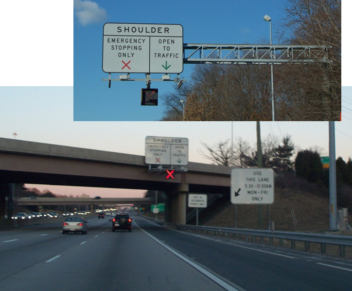
Hard-Running Shoulder on I-66 USA

Hard-Running Shoulder on I-66
EasyWay ITS Deployment Guideline TMS-DG04 Hard Shoulder Running available for download at: http://dg.easyway-its.eu/DGs2012
Although different from other highway control methods, the control of commercial vehicles, especially freight vehicles, can be an important part of traffic control. A freight control system will typically use GPS and mobile phones to manage the exact location of a vehicle and its freight at any given time. By extending this system, it can help to control the traffic by routeing the freight to a less congested route.
Driving difficulties for trucks and HGVs during snow for example, may lead to traffic congestion on the whole network. A possible solution may be to organise HGVs in convoys. This type of action requires:
EasyWay ITS Deployment Guideline TMS-DG06 HGV Overtaking Ban available for download at: http://dg.easyway-its.eu/DGs2012
The common objective of speed controls is to encourage drivers to travel at a safe speed or to improve traffic flow. They are a means to help drivers to travel at an appropriate, consistent speed taking account of the prevailing traffic or weather conditions. Persuading drivers to adopt more realistic speeds can have a calming effect and reduce erratic lane changing. The smoother traffic flow permits more throughput. In some cases these systems are also used to mitigate environmental effects, such as pollution or noise.
The measures are usually applied to sections of motorway that experience recurring congestion with gridlock and stop-start traffic conditions, including sudden stops that can be a source of accidents. It works:
Apart from handling recurring periods of congestion, speed regulation is a tool that can be used in all traffic conditions to gradually slow vehicles approaching a traffic incident or accident area.
Speed control systems are more common in Europe than in the USA or Japan. The major benefits relate to traffic smoothing, with improved throughput and a reduced rate of accidents. Displayed speeds are generally mandatory, rather than advisory - and enforced by speed cameras. They are aimed at reducing the range of individual speeds in non-congested situations and protecting the end of queues when congestion appears. In some systems the variable speed limit display is coupled with an automated enforcement system involving video cameras recording licence plate numbers, which issues citations to motorists who exceed the speed limit by a predetermined threshold. (See Enforcement)
The major benefits of speed control are improved safety and better journey times. Smoother traffic flow yields a slight increase in capacity, and a reduction in the number of accidents, especially rear-end accidents. Capacity effects are small and unable to solve bottleneck congestion – but in sections where demand approaches capacity, speed control is likely to delay the onset of stop-start conditions. In some cases, depending on highway conditions and capacity limitations, traffic flow breakdown may be prevented. These benefits are obtained by reducing the speed differential between vehicles and engaging driver attention.
This measure requires:
Traffic monitoring is indispensable: the operation can be fully automated but an operator must be able to recover control at any time if an unexpected event occurs – such as an accident or sudden deterioration in weather conditions. This measure is particularly suited to urban and suburban motorways, where the high proportion of routine drivers facilitates user compliance. The short length of controlled roadway (typically about 10 kilometres) also promotes adherence to speed limits.
EasyWay ITS Deployment Guideline TIS-DG04 Speed Limit Information available for download at: http://dg.easyway-its.eu/DGs2012
US Federal Highways Administration Engineering Speed Limits available for download at: http://safety.fhwa.dot.gov/speedmgt/eng_spd_lmts/
Speed limits that are legally enforceable may require the use of special VMS that closely resembles the official speed-limit sign mounted on overhead gantries. They can be supported by speed enforcement systems that use camera images to identify speeding vehicles and drivers. For some legal jurisdictions the approved VMS may need to be authorised in legislation in order to be enforceable.
Speed control is often associated with lane control because both measures generally use the same display equipment (gantries and signs). It can also be used for incident management or traffic control through work zones.
A similar effect may be achieved through variable speed advisory signs, which do not have to be legislatively enabled or enforced, although such signs may have lower levels of compliance. Motorists may claim confusion over the mixture of regulatory (fixed) and advisory (VMS) speeds.
The success of VSL requires that drivers understand, and comply with, the reasons behind changing the speed limit and the associated benefits. In most cases, the displayed speed limit should match the conditions that drivers encounter. There will be some cases when circumstances call for a reduced speed limit for which the reason is not obvious – for example environmental reasons, or problems downstream such as incidents or work zones. A study in the UK showed that when a reason is displayed on VMS alongside the speed restriction, there was a 20% increase in driver compliance with the restriction.
EasyWay ITS Deployment Guideline TMS-DG02 Variable Speed Limits available for download at: http://dg.easyway-its.eu/DGs2012
US Federal Highways Administration Variable Speed Limits available for download at: http://safety.fhwa.dot.gov/speedmgt/vslimits/
Controlled Motorways involve the application of several Automated Traffic Management techniques in combination – such as mandatory Variable Speed Limits (VSL), measures to reduce the frequency of lane switching through messages such as “Stay in lane”, speed controls and other traffic calming measures. In some systems (for example, in UK on the motorway around London and Birmingham), the variable speed limit display is coupled with an automated enforcement system (involving video cameras recording licence plate numbers), which issues citations to motorists exceeding the speed limit by a predetermined threshold.
Dowling R.G and Elias A. Active Traffic Management for Arterials - A Synthesis of Highway Practice NCHRP Synthesis 447 Transportation Research Board , Washington D.C. USA, 2013 download at http://onlinepubs.trb.org/onlinepubs/nchrp/nchrp_syn_447.pdf
Federal Highways Administration Active Traffic Management available for download at: http://ops.fhwa.dot.gov/atdm/approaches/atm.htm
EasyWay ITS Deployment Guideline TMS-DG04 Hard Shoulder Running available for download at: http://dg.easyway-its.eu/DGs2012
UK Government gateway to information on Managed Motorways / Smart Motorways available for download at: https://www.gov.uk/government/collections/smart-motorways
Although the situation may vary between different jurisdictions, the enforcement of traffic regulations often becomes relevant to the operations of the network. To ensure a smooth network flow, road users are expected to comply with regulations. Unless those regulations are self-enforcing (for example speed control through traffic calming measures) there needs to be a way to enforce the regulations.
Enforcement is not new – but recent technological advances have enabled new methods of automatic enforcement. The use of digital imaging and image processing, such as automatic licence plate recognition has had a dramatic impact.
Enforcement methods using new technology involve some kind of automatic detection. Sensors and digital cameras make it possible to better detect offences in speeding, red light violations and other evasions. The role of applying penalties is generally undertaken by an organisation responsible for enforcement (usually the police). The biggest benefit of these monitoring systems is said to be their deterrent effect. Enforcement systems are unpopular but will generally cause most users to become more cautious – increasing safety and improving the general throughput of the network. (See Policing / Enforcement and Law Enforcement)
One of the most frequent uses of automatic enforcement is the enforcement of speed limits using speed cameras. This requires a specialised speed camera that will measure the speed of each vehicle. In many cases, the system simply displays the speed to bring it to the driver’s attention, which is often enough to encourage them to reduce speed. In other situations, the system will take a picture of the offending vehicle for follow-up action. This would usually include capturing the number-plate of the car – but in some cases, it is necessary to include the picture of the driver, since in many countries, the vehicle owner may not be liable for actions by someone else using the vehicle.
The speed enforcement system can be permanent or a mobile unit. The information acquired by it will be used by the enforcement agency to apply penalties or (if necessary) prosecute the offender. Point-to-point journey times can be monitored by installing two cameras that are linked. Average speed monitoring is now commonplace, especially to regulate traffic speeds over extended sections, such as work zones. (See Speed Management)
Red light evasion ("red light running") at traffic signals can lead to serious accidents and it is extremely important that the traffic lights are observed. If non-compliance is high police presence or automated camera enforcement are two options. Automatic systems use a speed sensor (inductive loop) embedded in the road and a camera installed under the traffic signals. The red light and the vehicle sensor together will activate the camera and a picture taken of the offending vehicle. More advanced systems use the camera both to detect violations and to photograph the offence.
Where a railway (railroad) crosses a road or highway at a level crossing (“at-grade" crossing) there is always a potential safety issue. The level of protection varies considerably between different countries and regions. Where they are protected by gates, flashing lights or barriers – there is often in addition enforcement systems aimed at improving safety. For example, rather like red light traffic signal evasion, if a road vehicle enters a rail intersection during a warning period, it will be photographed.
ITS technologies are being explored to develop systems which can detect potential road/rail vehicle conflicts and help prevent collisions. For example, an Australian team is trialling an in-vehicle collision alert system which uses GPS and Dedicated Short Range Communications (DSRC) to warn vehicles if a train is approaching a crossing.
Heavy vehicles (trucks in particular) are often driven continuously by a single driver, accidents often result from fatigue. In many countries, there are regulations that specify the maximum amount of continuous driving time that is permitted. In order to enforce this, a black-box or electronic tachograph that detects the axle movement and possibly the location of the vehicle along time is often used. (See Driver Safety)
Since the road can only take a certain amount of weight per axle, it is important to ensure that all vehicles are not overloaded and are within legal limits. Otherwise, there will be significant deterioration of the road structure. Weigh-in-Motion (WiM) systems use a sensor on the road to measure each vehicle’s axle weight. When an overloaded vehicle passes, it will be notified to the enforcement agency which will take appropriate measures. (See Weight Screening)
Since most of violations may be contested in court, the systems must be adapted to meet the legal requirements of each country. In some cases, only the vehicle number-plate (licence plate) is necessary to catch the offending vehicle, while in others, the actual driver must be identified. For these systems to be effective and have the desired deterrent effect, they need to collect information that can stand up in court. Equipment must be type approved to certify that it operates to the required standard of accuracy and reliability. Type approval is important to avoid a legal challenge based on inadequate equipment and procedures. (See Equipment Certification)
Privacy is another important issue. It is extremely important to keep records confidential. In the case of identifying and notifying offenders, it may be necessary to capture photographs of offenders, which may lead to privacy concerns. (See Privacy)
One of the most difficult issues in implementation is proper coordination between the enforcement agency and the road network operator. In many countries, the road operators do not have the power to enforce regulations (this is usually police work). It is important to establish good working relations with the traffic police, to ensure that enforcement activities will facilitate better operation of the network.
Until a decade ago urban and motorway traffic control systems were considered separately – both from a technical and institutional perspective. As traffic demand increases the need for a seamless transition between systems becomes more important. The need for integration is particularly acute in situations where there are heavily trafficked motorways, expressways and parallel arterial road routes. The demand for reliable real-time driver information systems continues to grow. Increasingly the control of traffic on urban streets can no longer be treated separately from highway traffic control.
The Integrated Corridor Management (ICM) concept is one of the most significant developments in integrating ITS functions and resources between different organisations. Motorway and all-purpose arterial roads operations are closely coordinated from a single Traffic Control Centre (TCC) – or a highly integrated (linked) set of two or more TCCs. The objective is to achieve an overall balance of traffic between routes that serve a common set of destinations. This involves balancing demand through signal control and pro-active use of driver information, coupled with traffic diversions in some cases.
Integrated Corridor Management is designed to operate the motorways and the arterial road network and to optimise the use of both. It applies especially to a corridor with similar travel routes, that are broadly in parallel, serving similar destinations. Ideally, a single TCC would manage traffic on both motorways and the arterial roads, so that operators can shift resources – and demand – from one roadway to the other as conditions require.
An alternative to a single TCC, is to integrate several local TCCs by sharing data, images, information and decision making. Their managers will need Traffic Management Plans and Standard Operating Procedures (SOPs) that address balancing traffic along the corridor and managing traffic when an incident occurs. (See TCC Administration and Traffic Management Plans) Closely integrated operations are particularly beneficial in managing planned special events where the road traffic uses both the all-purpose arterial roads and motorways.
Public transport (transit) management is often an important element of network control – where for instance one or more bus and/or multimodal rapid transit stations are located within the managed corridor. In general though, purely transport operations (such as vehicle dispatch) are managed from a separate public transport operations centre. (See Operations & Fleet Management)
Freight customs clearance demonstrates the use of ITS in selected corridors. This could be a road freight or heavy goods corridor or a trans-continental or country-to-country corridor such as Mexico to Canada (via the USA) or Nicaragua to Panama (via Costa Rica). (See Freight Enforcement)
Planned events have a significant impact on Road Network Operations. They include sporting events, concerts, festivals and conventions taking place in permanent multi-use venues (for example – arenas, stadiums, racetracks, fairgrounds, amphitheatres and convention centres). There also include less frequent public events such as parades, fireworks displays, bicycle races, sporting games, motorcycle rallies, seasonal festivals and milestone celebrations at temporary venues.
Five categories of special events can be identified based on their characteristics:
These are all different forms of traffic incident and often require major planning for traffic management, preparation and response. They are distinct from other incident types in a number of important respects – one being that they involve a new set of stakeholders that do not play a part in most other types of incidents and emergencies. They include:
Planned Special Events can have a significant impact on travel safety, mobility and journey time reliability across all the transport modes and roadway facilities. Managing travel for these events involves:
Events such as the London Olympic Games require considerable planning. Traffic lanes dedicated to vehicles carrying competitors to their events were introduced, a command and control centre was established and additional roadside hardware was deployed (mainly VMS and vehicle detection equipment) – (See Case Study: London 2012 Olympics)
The practice of managing travel for Planned Special Events should target the following objectives:
The goals of managing traffic and travel for these events are as follows:
Traffic Incident Management (TIM) is the response to traffic accidents, incidents and other unplanned events that occur on the road network, often in potentially dangerous situations. The objective is to handle incidents safely and quickly, to prevent further accidents and restore traffic conditions back to normal as quickly as possible. It requires the deployment of a systematic, planned and coordinated set of response actions and resources.
Traffic Incident Management proceeds through a cycle of phases starting with immediate notice of possible dangers or problems ahead – as soon as an incident occurs – in order to forewarn drivers and prevent accidents.
Incident warning and management have two main goals – to:
Incident management requires planning, a response that is proportionate, safety at the scene of the incident and recovery. It requires attention to three main aspects – in order of priority – safety, mobility of traffic flow and control and repair of damage.
To understand how control strategies and network operations can reduce the negative impact of incidents, it is important to understand the timeline and different stages of incidents, as shown in the diagram below.

Timeline for a Typical Traffic Incident - Source: Wallace, et al., 2007/2009 - Note: “wrecker” is an American term used to refer to “recovery vehicle or team” or “breakdown truck or tow-truck provider”.
The diagram might represent a collision on a motorway, a spill of materials or a disabled vehicle - resulting in the need to close one or more of the running lanes. All steps will not occur in every incident - and there may be other interwoven relationships – but the diagram represents the typical sequence for most moderate-to-serious incidents. The steps are shown in a staggered fashion simply to illustrate that the incident timeline is not uniform (the time increments are relative – and not to any scale).
The duration of particular stages in the incident are represented by the letter pairs in the diagram and are listed below. For example, the duration of the incident itself would be from point A on the timeline to point M, while the total time the incident is having an effect on traffic is from A to N – with the time elapsed to point N often proportionately much longer than shown.
Common phases of an incident are:
Although not evident in the diagram, the recovery period is frequently longer than the duration of the incident itself. Incident recovery can be four-to-five times longer. This means that for every minute that can be trimmed off incident detection, verification and/or clearance, up to 5 minutes of recovery time can be saved for traffic to get back to normal.
Avoiding secondary incidents is of paramount importance because they start the incident response cycle all over again. The aerial photograph below illustrates this point. The original incident that caused the multiple vehicle pile-up was a car that was stationary due to its engine overheating – which blocked a traffic lane in the direction going “downstream”. The stationary vehicle was the cause of one or two collisions but many more collisions on both sides of the highway occurred because a vehicle responding to the incident attempted to bypass the traffic queue and reach the incident by travelling the wrong way on the opposite side. The example shows that secondary incidents can in fact be more serious than the original incident.

Secondary crashes resulting from a "wrong-way" (contra-flow) response - Source: Wallace, et al., 2007/2009, originally from the collection of John O’Laughlin.
All agencies must work closely together to quickly detect an incident, and to verify, respond and clear it in as timely and efficient a manner as possible. ITS in general and the Traffic Control Centres (TCCs) in particular will play a part at each stage. (See Urban Operations and Highway Operations) The emphasis must be on the rigorous application of the 4-Cs of incident management (Communication, Cooperation, Coordination and Consensus) and close inter-agency working, through Traffic Incident Management (TIM) teams. Traffic Incident Management Teams and Safety Service Patrols are vital elements of a good traffic incident management programme. (See Incident Response Plans)
Clarity in assigning roles and responsibilities to the Traffic Incident Management (TIM) Team, the Mobile Safety Service Patrols and tow-truck providers during traffic incidents cannot be understated. Even though the TIM team may not be an active participant in the response to a particular incident, it has a key role to play in formulating the policies, practices and training that go into it. TIM members will include the first-line responders or organisations that provide direct support. Mobile Safety Service patrols and tow providers are also active participants. (See Mobile Patrols)
Typical use of ITS devices and the roles and responsibilities of the TCC and Mobile Safety Service Patrols are summarised in the two tables below for different stages of an incident. In these tables there is no implied sequence of actions within cells – instead they are typical actions that might be taken.
|
|
Roles and Responsibilities |
||
|
Incident Stage |
Use of ITS |
Traffic Control Centre |
Mobile Safety Service Patrol |
|
Detection |
|
|
|
|
Verification |
|
|
|
|
Response |
|
|
|
|
|
Roles and Responsibilities |
||
|
Incident Stage |
Use of ITS |
Traffic Control Centre |
Mobile Safety Service Patrol |
|
Roadway Clearance |
|
|
|
|
Incident Scene Clearance |
|
|
|
|
Recovery |
|
|
|
|
After Action |
|
|
|
Protection of personnel and field equipment from vehicle impact is of primary importance during any traffic incident or on-road emergency. Use of high-visibility vests or uniforms by incident response teams and maintenance workers should be mandatory. High-visibility markings on response vehicles and maintenance trucks helps to avoid collisions. Buffer zones around incidents or maintenance work create a safety zone – although care needs to be taken to balance safety with keeping roadway capacity available for traffic flow. Standard practice differs considerably from country to country and local practices should be followed where they exist.
All means of travel and traffic information can be used to provide timely and accurate information to travellers about the nature and location of incidents and maintenance activities (See Travel Information Systems). Automatic Incident Detection can support queue protection warnings to the approaching vehicles up-stream (See Automatic Incident Detection).
Several innovative initiatives have been used in Europe and South America, as follows:
The responders’ first priority must be the safety of themselves and the people involved in an incident. Incident scene management, particularly on high-speed roadways, often involves closures of lanes and discussions about when to re-open lanes to allow traffic to pass an active incident scene.

Creation of a Safe Zone around the incident. Courtesy Georgia DOT.
These decisions will be made by the incident controller (commander), who has powers to control and direct traffic (usually the police, highway or traffic patrol). ITS can assist with the decision making process. CCTV camera images – or the transfer of information from them – can be delivered to the commander either verbally or visually via tablet computer or a wireless mobile device – giving a “higher-level” view of surrounding conditions than available from the ground. Traffic and Travel Information is provided to inform drivers about lane closure status – enabling them to make more informed choices about making diversions or delaying or rerouting a trip. Less traffic helps ensure the safety of responders. (See Travel Information Systems)
Mobile Safety Service patrols play a vital role in safety. They help to manage the scene and alerting drivers who are approaching the back of the queue, help avoid secondary incidents as well as alerting passing drivers – improving the safety of the responders at the scene. VMS, Portable Dynamic Message Signs (in particular those mounted on Safety Service patrols) and other driver information delivery systems can help in providing a safe incident scene and protecting responders engaged directly in incident recovery. (See Use of VMS)
Many of the urban high-speed toll roads in South America have near total coverage by CCTV. This allows the TCC staff to monitor and record the entire response effort. These videos can later be used as a valuable training tool. CCTV also enables TCC staff to monitor upstream traffic to warn of any developing situations or to inform about secondary situations as they develop. (See CCTV)
It is sometimes difficult to determine whether a situation on the road will deteriorate into a major traffic incident or even a full-blown emergency. Some operational tasks for incident management described here may appear disproportionate to the number of incidents that occur. The crisis management checklists developed by the planning teams will help to optimise service, time and efficiency when an emergency occurs. If the impact of the incident is widespread several control centres may become involved in responding – and coordinated action will be needed. (See Incident Response Plans and Emergency Plans)
Work zones - due to road, bridge and tunnel construction and maintenance work have a negative impact on Road Network Operations. ITS and other techniques are used to minimise the negative impacts and keep traffic moving through affected zones as efficiently and safely as possible, for both for travellers and workers. This is especially important for night-time work, which is becoming increasingly common on the highways.
A number of measures are used to minimise worker exposure to motorised traffic and to safeguard road users from the construction and maintenance work. They include:
Safety cannot be achieved by preventive measures alone. It is important to constantly monitor the traffic situation, weather conditions and the specific construction or maintenance activities taking place – and respond as necessary. This can be achieved through the establishment of an integrated traffic management and construction operations centre. Often a dedicated operations centre with tow-trucks for incident response is set up.
In safe and stable traffic flow, traffic lanes must be observed so that proper segregation between vehicles of different speed is maintained. This can be done through the use of road studs, "cats eyes" or some other physical markers in the lane separation – which the driver will sense if the vehicle strays into a neighbouring lane. This may either trigger a warning or – in vehicles with advanced equipment – a warning could automatically lead to corrective action by the vehicle itself. Cameras or lasers, can be used to sense vehicle intrusion into closed lanes, which could otherwise endanger workers. (See Warning and Control)
ITS technologies provide many opportunities for monitoring and managing work zone operations – but are not a way of saving on fixed signing and traffic cones. ITS has benefits when signing and coning in preparation for roadworks – and when the roadworks are live and an incident occurs. A reliable source of power will be required, such as a portable generator.
ITS applications have been used to measure spot speeds in work zones. More recently APNR cameras are widely used to support average speed enforcement – with good compliance. Other ITS technologies are used to collect data that accurately reflects travel conditions through work zones – and, more recently, real-time monitoring of traffic conditions.
Use of ITS in work zones is not limited to urban areas. Temporary ITS devices, such as Portable Dynamic Message Signs (PDMS), Highway Advisory Radio (HAR), trailer-mounted cameras and sensors – can easily be deployed in a rural work zone where permanent ITS does not exist. Several commercial companies provide services that may include these devices, which communicate their data and images to a remote location where they are monitored (along with images from other locations). If issues arise, those monitoring the cameras can contact local law enforcement and transport officials who are able to respond.
In summary, ITS technology can be applied in work zones for the purposes of:
Many applications serve a combination of these purposes to:
Some regions have automated enforcement in work zones. The data and information necessary to support enforcement action can be collected from the use of Bluetooth, CCTV cameras, buying third party data and coordination with the TCC.
Most work zones are relatively short-term in nature, but some maintenance and construction work is long-term. Early deployment of ITS can be effective in supporting diversions, managing incidents and mitigating capacity reductions.
So-called “smart” work zones employ a combination of data sources to measure journey times through the work zones and are becoming commonplace in many countries. Real-time ITS supports a wide array of innovative applications that include active management of work zones based on observed traffic conditions. These capabilities are used to extend work hours and maintain acceptable journey times. Work is curtailed when journey times exceed certain thresholds. Work zone managers can be warned when travel speeds are dangerously high and a police presence may be needed.
In the UK work zone contractors have to limit their possession of the roadway for maintenance work during peak times. One innovative solution to this involves the use of Portable Dynamic Message Signs (PDMS) - with built-in traffic detection to monitor traffic demand. The ITS equipment allows the contractor to maintain lane restrictions longer – until the volume of traffic requires them to be removed. The increased time for site occupation allows longer work periods, improving productivity so that the works finished sooner. Motorists benefit from a reduction in the overall period of disruption.
Most emergencies are characterised as “short” or “no-warning” incidents or events, such as sudden major storms or other severe weather events, airline or train crashes, earthquakes, flash floods or terrorist threats. The less frequent, but usually more devastating events are “with-warning” emergencies, such as a hurricane, tsunami, tidal wave, flash flood, major river flood or spreading wild fire. The response to these different levels of emergency can be very different.
Having days to prepare for something like a hurricane or flood allows agencies to alert the public in a timely way, to stockpile or reposition resources, to muster additional resources and ultimately, prepare for evacuation. Emergency managers and responders can be more proactive in their responses.
When the warning is short, or non-existent, the response is almost entirely reactive. This is why Emergency Management protocols require extensive planning, preparation and training. Transport agencies are advised to be more involved in development of Emergency Operations Plans. (See Emergency Plans)
There are two aspects of primary concern:
When the transport system itself in not materially impacted – by a pandemic for example – the transport network becomes the focus of responding agencies. Roadways, public transport, trains, boats, ships and airplanes become the means of avoiding or evacuating from the emergency.
For traffic operations, transport managers can take the following actions to assist emergency managers:
When the transport network is directly impacted by the emergency it will be less effective in serving the emergency and its managers. This is where emergency pre-planning and preparation within the transport agency are so important.
In the USA, the Florida DOT and several coastal urban areas in this hurricane-prone state, stockpile traffic signals and generators in order to be able to replace damaged signals and to control restored signals in the absence of commercial power. Portable Dynamic Message Signs (PDMS) can temporarily replace damaged VMSs. Temporary Highway Advisory Radio units can be used for a similar purpose – but need to be supplemented by fixed signage that informs travellers of the HAR station frequency.
Effective communications is essential between Traffic Control Centres, Emergency Operations Centres and other centres where data and information about the emergency is collated (“Fusion Centres”) but not always fully achieved. Often it is because of differences in the jurisdictions of different transport agencies, emergency mangers and security people. Law Enforcement Dispatch Centres and Emergency Call Centres (999) can be included in the mix. In some regions this problem is exacerbated by the lack of open, non-proprietary communications protocols.
All can be connected by telephone and the Internet but co-location or direct electronic linkages for data, camera images and information sharing is more effective.
Extreme emergencies might require evacuation of residents and visitors, sometimes from large areas. Because of their extreme nature, a region can never be fully prepared to meet all of the challenges – both physical and institutional – that arise. From a traffic perspective, any evacuation is going to severely threaten the capacity of the transport network to handle it. Most of the actions that agencies can take to mitigate the negative impact of an evacuation and help keep traffic flowing require changes in the physical infrastructure or the use of mass-passenger modes.
Public transport (transit), school buses and trains can be used to transport evacuees, particularly those that are mobility-challenged – such as patients in hospitals and other health-care facilities, students, the homeless and prisoners. These arrangements take time to organise and carry out, and require good inter-agency cooperation. ITS can assist to a some extent – for instance by giving bus drivers the same traveller information that other vehicle occupants receive.
In urban areas, entire city streets can be shifted to one-way operation to accommodate large numbers of vehicles escaping harm’s way. These require large numbers of police or military officials to control traffic. ITS does not have a significant role here, other than to minimise the conflicting guidance that traffic signals might indicate (such as green displays in the “wrong" direction).
These can be deployed effectively to use the inbound capacity for outbound evacuating traffic. Emergency contra-flow lanes are often in rural areas. ITS can contribute through VMSs to reinforce contra-flow guidance, CCTV to monitor the traffic - and the provision of travel information to inform travellers. Most public information will be generated by the incident command centre. The increasing use of probe vehicles can give transport and emergency managers data on journey times.
In a few instances, devices such as motorway ramp-closure gates can be deployed for use in contra-flow operations. Normally motorway entrance ramps have to be closed to traffic.
The photograph shows a contraflow operation in Houston, Texas before Hurricane Rita in 2005. Contraflow requires a great deal of advanced planning, physical preparation (such as the cross-over lanes), large teams of officials for implementation, and time to deploy and later restore to normal. A number of USA states on the Gulf and Southeast Atlantic coasts - as far north as Baltimore – have Contraflow Plans, but most regard the measure as a last resort.

Courtesy Texas DOT.
Security threats are not very different to natural emergencies – except that they can have a broader range of impacts, such as cyber/Information Technology (IT) attacks, Chemical, Biological, Radiological, Nuclear and Explosive (CBRNE) threats and other terrorist actions. (See Network Security)
Much of the advice for emergency response applies to security threats – particularly in respect of threats to the transport network (for example the 1995 sarin gas attack on the subway in Tokyo in Japan and the 2004 train bombing in Madrid in Spain). The role of the transport network to respond to the threat is relevant – for instance, the closure of access to Manhattan Island in New York following the 9/11 attack on the World Trade Centre’s Twin Towers or when suicide bombers struck in Central London in 2005.
This supports the proposition for linking together Traffic Control Centres, Emergency Operations Centres and Information Fusion Centres. Emergency and security responders need to know the status of routes to and from the threatened area – both for responders and rescue teams.
A challenge to emergency managers is to avoid unnecessary evacuations. Following Hurricane Rita in Texas, the regional TCC’s (TranStar) spokeswoman, Dinah Martinez, said at a town hall meeting “During the disastrous Hurricane Rita exodus, part of the problem was that for every five people who evacuated, four of them probably didn’t need to." Traffic and travel information systems can be used as a tool to discourage people from leaving unnecessarily.
The opposite of evacuations is the confinement of people within an area – for example to contain a potential pandemic. In this case CCTV can show where vehicles are travelling when they should not be – and travel information can augment public safety notices.
Driving can be heavily affected by adverse weather conditions, such as heavy rain, high winds, dust storms, snow, fog and icy roads. It is important to inform drivers of extreme weather conditions in advance so they can change their travel plans or proceed with caution. Warnings on conditions that may be hazardous – such as high winds, icy roads or torrential rain – are especially helpful.
Road Weather Management (RWM) strategies provide:
For these purposes, supporting technologies include:
In adverse weather conditions, any intervention by the road operator must be implemented and co-ordinated efficiently to maintain the viability of the road network. In a flooding situation, for example, it is necessary to determine back-up solutions for the provision of driver information in the event of power or telecommunications failure. Procedures should include identification of areas at risk of flooding, the implementation of real-time monitoring systems incorporating threshold alarms and the specification of operations on receipt of alarm.
Post-emergency phases are equally important and include:
A successful RWM programme requires both prevailing and predicted weather and traffic information. The data required to derive this information needs to be collected from multiple sources. Many road authorities (as well as other industries) subscribe to commercial weather forecasting companies that provide timely, location-specific forecasts. They can do this because they draw their data from multiple sources, including the weather services – and integrate the results. Some have their own forecasters available on call to clients for consultation.
A self-evaluation and planning guide was developed, as part of an Federal Highway Administration study in the USA on integrating weather into TCC operations. The aim was to help TCCs evaluate their weather integration needs and develop appropriate implementation strategies. The guide assists the TCCs to identify weather conditions, weather impacts – and current levels of weather integration in the TCC and the need for enhanced integration.
In countries prone to severe winter weather, preventive action and crisis response may consist of handling both major disruptions to traffic (often lengthy) and frequent but brief disruptions due to weather conditions such as freezing rain, black ice or snow. The network management objectives will be to:
Winter service is based on data gathering (forecast and real-time), coordination, response and information dissemination. It requires a thorough knowledge of the network and its critical points, specific weather information, a sound knowledge of all stakeholders (such as weather forecasting services, suppliers of de-icing material), trained staff, equipment and materials (such as salt) – and good communication tools.
Traffic operations understandably deteriorate when there are inclement weather conditions. Automation of data collection of such conditions enables facility managers to respond to adverse conditions more timely and efficiently.

Source: http://ops.fhwa.dot.gov/weather/mitigating_impacts/technology.htm
A Road Weather Management (RWM) system (also known as Road Weather Information Systems (RWIS) and Weather Responsive Transport Management Systems (WRTM)) - consist of a set of sensors or Environmental Sensor Stations (ESSs) (See Weather Monitoring). These weather stations can detect and report a number of environmental measures that affect roadway operations, such as:
Perhaps the most common use of RWM is in cold climates and/or mountainous regions where snow and ice are commonplace. Maintenance operators use the data from strategically placed ESS units to determine the optimal time to deploy dispensing trucks for salt and grit and snow ploughs – and to determine the best treatment strategy – such as whether to use brine, salt or sand. This helps avoid premature or incorrect deployments, saving valuable materials and minimising vehicle operating cycle times, as well as reducing environmental impact.
Maintenance staff frequently use fleet-management systems to locate their vehicles, including where they have and have not yet ploughed or treated. In many regions, weather conditions can vary considerably from place to place. RWM may be used to help prioritise where and when to send equipment.
RWM technologies are also used to detect conditions that may be hazardous (such as high winds or flooding) – or that may impact roadway operations. Sensor systems are used to detect other conditions that cause reduced visibility – such as fog, smoke, blowing dust or sand and blizzard (white-out) conditions on roadways.
Wind-speed sensors on exposed roadways and bridges alert TCCs about when they should consider issuing travel advisories for trucks and other large vehicles. When wind speeds are particularly high it may be necessary to impose a maximum speed and in some cases close the bridge to all traffic.
Water-level sensors can alert managers when floods are threatening, particularly for flash-floods in normally arid climates or in built up areas when streams and rivers overflow.
Road operators should ensure that drivers, travellers and other stakeholders (such as public transport operators, school bus and ambulance services and control rooms for delivery and haulage operations) have access to timely, accurate and relevant information on current and forecast road and weather conditions. All forms of traveller services can be used to disseminate messages on snow, ice, rainfall (precipitation), visibility, wind and extreme weather events using VMS, HAR, websites, 511 traveller information systems and other methods. (See Traveller Services)
Integrating weather information into TCC operations allows the development and use of decision support to better manage the traffic under adverse conditions, to dispatch maintenance crews and respond appropriately and in a timely manner to weather-induced problems. Decision support built on integrated weather and traffic information into traffic analysis tools and TCC operations allows more proactive – rather than reactive – management. (See Planning and Reporting)
This adds value to road operations because it makes the actions needed to mitigate adverse weather more efficient – maintaining traffic flow in as orderly a fashion as possible under the circumstances.
Probably the most significant technological development since the emergence of ITS in the 1990s is the rapidly advancing world of coordinated, or as sometimes called – “connected” vehicles and “connected” infrastructure. Vehicles in wireless communication with each other and with roadside devices share data and help avoid vehicle-vehicle collisions, red-light running crashes and many other benefits. (See Warning and Control)
To the extent that this currently happens, the contribution of ITS to traffic control will make increasing use of in-vehicle equipment to affect both the driving task (to reduce headways and boost lane capacity) and the route choice (to optimise network capacity). Policies that are aimed at lowering and spreading travel demand by influencing travel mode, time of departure and route choice will also play an increasing role.
Connected vehicles will, in the future, be able to alert drivers to unseen dangers on the road ahead, such as icy roadways or incidents. These communication capabilities applied to ITS are referred to as vehicle-to-vehicle (V2V), vehicle-to-infrastructure (V2I) – or generically, V2X. These emerging technologies have a key role to play in Intelligent Transport Systems and have the potential to greatly enhance ITS functionality. In the meantime, transport agencies and providers can only continue to make the best use of, and draw benefits from, the ITS technologies they currently have in place.
These developments make possible the autonomous operation of vehicles, where computers control the vehicles and enable collision-free, close proximity, high-speed traffic operations that will more than double the capacity of roadways. (See Smart Vehicles)
As vehicles communicate with each other – so too, might a TCC communicate with them. This makes possible the establishment of a traffic management strategy known as Dynamic Traffic Assignment (DTA) – where a central computer with near perfect “knowledge” of traffic and weather conditions throughout the network can dynamically determine the optimal route (or, pre-trip mode of travel choice) for an individual. It is intended to be capable of directing equipped vehicles to follow the optimal route. Emergency services can also be given priority in real-time to reach an incident scene quickly and efficiently. Vehicles on conflicting routes could be commanded to give way to emergency vehicles.

Diagrammatic representation of Vehicle Communications - Source: http://www.its.dot.gov/connected_vehicle/connected_vehicle.htm
Most of the technologies needed to accomplish this vision already exist. Considerable investment has already been made in Research and Development across the world. As long ago as 1997, a demonstration of automated roadways was conducted in San Diego in California. Connected Vehicles have been successfully demonstrated in many other locations across the world, as illustrated in the TMC of the Future video Video: TMC of the Future
"Any sufficiently advanced technology is indistinguishable from magic." - Arthur C. Clarke
Demand management for road transport is one way of reducing congestion. This can involve relatively straightforward access control techniques or categorising vehicles (for example by their number plates) to restrict flows entering a given area. More intensive measures include charging for use of the road during congested periods, or the introduction of special high-occupancy vehicle (HOV) lanes.
There seems to be no fixed condition for the use of demand management. In most cities and regions that suffer from traffic congestion some method of demand management is undertaken. In general terms the severity and directness of the methods taken are proportional to the congestion problem that the area is facing.
Demand management covers all the measures that aim to limit the consequences of increased congestion and a decreasing level of service on a route. This is carried out through actions related to the local mobility policy, such as improving traffic distribution through time or encouraging users to modal transfer. Demand management is close to some traffic management actions that are mutually complementary. Operational tasks related to demand management will be integrated with a more global and multi-modal mobility policy with the road being part of it.
A number of strategies exist for reducing traffic demand by encouraging changes in traveller behaviour. Some examples are:
With the exception of the last, these programmes are implemented through marketing campaigns and do not require technology tools for the most part.
A more direct approach is through the use of pricing incentives, or disincentives. Increasingly electronic ticketing and electronic payment methods are utilised to pay for transport services and ITS technologies can be used to keep track of transactions, clients and other data useful for improving operations and providing customised services. (See Congestion Charging and Variable Pricing)
Examples are:
Major urban congestion charging schemes have been introduced in Singapore using Electronic Fee Collection (EFC) and in London (UK) using a variety payment methods and a permitted list, backed up by “smart” camera enforcement. (See Back Office Arrangements and Enforcement)
There are other methods of demand management, which may not directly involve the road authority, for example the promotion of park-and-ride, ride share schemes and public transport. (See Transportation Demand Management) Subsidies for these programs may also be helpful. Another method would be to increase the usability of public transport through common passes or smartcards. (See Passenger Fare Payment)
It can be argued that various urban renewal schemes or master plan development, such as the creation of work places closer to the residential area would be a part of an overall demand management policy. This would go far beyond the normal role of a road network operator and is not considered here.
One of the most frequently used measures of demand management is information provision. This could be information provision before the trip, or information provision on the trip. Users may look up the traffic information through various methods, such as the Internet, conventional media such as TV or radio, smartphones, VMS and on-board units. Based on the information, the user would make an individual judgement to take another route, thereby reducing the demand for a certain section of the network, or change to public transport (as in the case of park and ride systems), change the time of the trip, or not use the car at all for the trip. (See Pre-trip information)
Journey planning and travel information provision is available in most cities. This is a fairly simple method that can be implemented for a relatively low cost. It is not restrictive and it leaves the actual decision on whether and how to travel to the users themselves.
Implementation issues: Information provision itself does not present significant implementation problems, although there are issues to do with information coordination and collection, information processing and the dissemination method that need to be worked out. (See Travel Information Systems)
On-trip information provision does not necessarily decrease the total traffic demand. More likely, it will simply re-channel the demand into a different part of the network. Therefore, in cases where the entire network is congested or there are no alternative route or transportation methods, the effectiveness of this method will be limited.
Another problem associated with information provision is the undesirable flow of traffic that may occur as a result. In order to avoid the traffic congestion ahead, many drivers divert onto side roads creating through traffic in a residential district or a school zone, increasing the risk of accidents. In these cases there is a danger that information provision may create more problems than it would solve. Since this is hard to foresee, a careful monitoring of the traffic pattern after introduction is essential.
The technical development of electronic payment has made it possible to apply the concept of a road toll beyond the recovery of operational and infrastructure costs. Road pricing is a tool for traffic management, especially in urban areas that experience heavy traffic. The objective is to spread traffic throughout time in order to avoid saturation in a controlled area or on a toll motorway, bridge or tunnel. More efficient use of the transport system is achieved if people are persuaded either to change their time of travel away from peak periods, or shift from travelling by car to using an alternative travel mode. Often the money raised from road pricing is applied to the improvement of public transport. (See Congestion Charge)
Where there is an imbalance between supply and demand, the standard economic solution for any scarce resource is to let the market decide. The market would bid the price of that product up or down until the demand matches the supply and the market clears. Traffic congestion is evidence of an imbalance between the supply and demand for roadspace, and so controlling it through pricing is an obvious solution. Economists will assert that road pricing is an extremely sensible and rational measure for dealing with an excess of traffic demand. For toll roads, this would seem to be a textbook solution.
A road pricing system needs a tolling and payment system with back-office arrangements that have the capability to charge by distance, by type of vehicle and so that charge can be varied, up or down, to reflect conditions of time and place.This was impractical until the development of electronic payment systems and Electronic Toll Collection (ETC) in particular, since with a manual system it is difficult to implement a different price (toll) for a given time period. Electronic payment systems allow flexible charging, which can be on the basis of time, place and distance. (See Electronic Payment)
With ETC variable pricing is technically more straightforward but it is not adopted as widely as it could be. Generally there is hostility from road users whenever a road pricing scheme is proposed. The main argument against it concerns fairness and equity - a perception that road pricing only allows more wealthy people to use the road. It can achieve the goal of easing congestion by limiting the demand, but the impact on poor people is disproportionate. There are counter-arguments but the perceived inequlaity is an obstacle that is difficult to overcome politically. With some notable exceptions, politicians have been unwilling to take on this issue. Consequently, this method as a demand management measure is implemented in relatively few places around the world.
Whatever the aims of a road pricing policy, from an operational perspective it is necessary to minimise user inconvenience when using the payment system. Electronic payment methods can limit the discomfort and improve road safety and efficiency. (See Payment Technologies and Process)
Variable tolling is an example of road pricing that operates to spread traffic over time in order to avoid gridlock at times of peak demand or during heavy seasonal travel. Alternatively it can be used to generate more traffic by giving a discount on the usual toll when the volume of traffic is low.
The principle of variable tolling is to raise tolls during peak periods (“red” periods) and lower them during periods of lighter traffic (“green” periods). Implementation is based on publicity and information dissemination:
In the case of free-flow toll facilities, the toll level can be changed throughout the day, which requires real-time information to road users, informing them of the current toll rate through VMS.
Some precautions are required to:
Variable tolling can be cumbersome to manage (for example adaptation of toll equipment and the need for user information). Higher peak-period tolls are unpopular and are viewed as a hidden attempt to increase total revenue. Success is as dependent on user acceptance as on the technical relevance of the measures introduced. It essentially depends on three factors:
The application of this measure on toll-roads in France, showed a decrease in peak period traffic (average reduction of 10 percent) with no reduction in total demand or lasting diversion of traffic to parallel roads.
Variable tolling has become more common with the use of smartcards and electronic tags. As ETC is adopted more widely the integration of new ETC systems with older systems becomes a problem. As ETC systems are improved or upgraded, compatibility with the old units becomes an issue. This can be handled through good equipment standardisation, agreements between operators on evenue sharing and agreement on a consitent interface, for example on the classification of different vehicle types.
There is no certain way of reducing traffic demand - it is often a diverse and difficult issue. Various methods need to be combined in response to local requirements. Even in the simplest method of information provision, consultation with and coordination of the parties involved is essential, with careful monitoring of the effects of controls. This is particularly true for direct methods of demand management by means of access control.
A common method is to remove through traffic from a controlled zone by restricting entrance to that zone only to users who have an electronic pass, or through vehicle licence-plate recognition. (See Policing / Enforcement) This is typically done by signs that announce the restrictions and a gate or barrier at each entrance of the zone where the electronic pass or vehicle licence plate can be checked. Checking is sometimes done manually although there are ways to do this automatically through the use of ANPR and "permitted lists" (lists of authorised vehicles), or with on-board transponders as a basis for enforcement.
Entry restrictions are always politically difficult to implement, although perhaps not as difficult as road pricing. The issues commonly associated with this restriction are political, the cost of equipment or staff required to enforce the restriction and the numbers of users who seek exemption or try to evade the system. In the case of a High Occupancy Vehicle (HOV) lane, for example, there have been cases where people are paid to ride in the user’s vehicle. Also, the restriction of traffic may have negative effects on the area’s economy, which may be a source of criticism. The challenge always is to reduce vehicular traffic without limiting productive activities within the area.
Ramp metering is a method to restrict the entry of vehicles to a motorway from a selected on-ramp in order to maintain free-flow conditions on the main carriageway. The implementation is fairly easy, since the number of ramps is limited and they can be controlled by the network operator. Ramp metering and entry restriction are widely used in the USA, either based on the numbers of vehicles, or selectively (for example High Occupancy Vehicles (HOV) only). (See Highway Traffic Management)
Ramp metering is becoming increasingly common outside USA. Implementation issues are not large, although there can be resistance from some users. An issue which sometimes needs careful attention is the storage capacity of the ramps, since queuing which tails back onto surrounding main roads may cause congestion to spread and reduce the level of service on the arterial roads.
The purpose of mode transfer is to create conditions that foster greater use of public transport (modal shift) to counter increased traffic volumes and congestion during rush hours, or following a major capacity reduction over an extended period (with risk of major daily traffic jams over several months). Both situations can lead to an acute drop in road network service levels due to a lack of roadway capacity.
The measure is attractive:
Mode transfer incentives can also be used in response to other situations such as poor air quality and a forcast increase in air pollution.
The objective is to promote greater use of public transport in order to reduce the number of vehicles on the road. A common approach is the use of information to the user in real-time on public transport services and on the existence of multi-modal journey transfer points, such as "park-and-ride". (See Transportation Demand Management) This is done through journey planning websites, and in real-time with VMS or in-vehicle information devices (conventional broadcasting, RDS-TMC, route guidance systems). (See En-Route Information)
The anticipated problems (for example daily traffic jams, or lengthy delays) must be well-publicised in advance or braodcast in real-time through travel aid and user information measures (VMS or in-vehicle equipment, smart-phone text messages and social media).
Car pooling or use of public transportation can be encouraged by upgrading the service frequency and capacity, especially during rush hours.
This measure requires preparation involving all partners starting several months before the planned disruptions are scheduled. (See Traffic Management Plans) It is implemented in the following stages:
Publicity need to convincing and persuasive enough to overcome reluctance and rigidity in the response of road users. Success also depends on:
Different strategies are needed to achieve a mode transfer for freight. Integrating actions on freight management. This may be seen as a long-term measure within the road network operations strategy. particularly when the aim is to shift goods off the road amd onto other modes. (See Users and the Delivery Process)
Across the world 1.24 million people lose their lives each year on the roads. A further 20-50 million suffer non-fatal injuries. The United Nations (UN) Decade of Action for Road Safety (2011-2020) aims to halve annual road fatalities by 2020, compared to 2010.
Advanced Information and Communication Technologies (ICT) can contribute significantly to road safety, enabling sophisticated ITS applications to be deployed to prevent accidents, reduce their severity and improve survival rates. Road authorities are the major public stakeholders in ITS and largely responsible for their safety aspects.
Far-reaching developments include in-vehicle control systems and roadside information, traffic control and enforcement – which impact on the safety of drivers, road workers, cyclists and pedestrians, all of whom are particularly vulnerable. For example:
Many ITS systems have been developed with the primary aim of increasing road safety – such as improved vehicle control in critical situations and automatic alerts for assistance after an incident has occurred. (See Driver Support)
The following systems are already implemented by many road authorities:
Other systems, for which safety was not the primary motivation, will nevertheless affect safety because their use results in changes in travel and driving behaviour – for example travel information systems giving forward warning of an accident ahead may prevent the occurrence of secondary collisions.
Systems aimed at improving safety generally have a positive influence on drivers and road users - but they can also have a negative impact – for example through behavioural adaptation or risk compensation. (See Human Factors)
The WHO report presents road safety information from 182 countries across the world, accounting for 99% of its population. It provides the baseline for the UN Decade of Action for Road Safety 2011-2020. Traffic injuries are the eighth leading cause of death globally, and for young people (aged 15-29) they are the leading cause of death. At the national level, road traffic injuries result in significant financial costs - particularly for developing economies. The costs to low-and-middle-income countries is estimated at being between 1–2 % of their gross national product - over US$ 100 billion a year.
Unless urgent action is taken, WHO suggests that by 2030 road traffic deaths will become the fifth leading cause of death. Currently only 28 countries, covering 7% of the world’s population, have comprehensive road safety laws for five key risk factors: drinking and driving, speeding, and failing to use motorcycle helmets, seat-belts and child restraints. Over a quarter of the fatalities are among pedestrians and cyclists – but to date, these road users have been neglected in transport and planning policy.
Reduction in accidents, and in particular injury and fatal accidents, is a primary focus of many ITS deployments. Integral to these is an understanding of how the existing traffic situation (driver behaviour, vehicle dynamics and road environment) relate to safety. Also key is understanding that an ITS scheme which is not in itself targeted specifically at road safety – may nevertheless result in changes in the level of safety as an unintended side effect.
Deployment of ITS can alter the balance of accident types. It is not uncommon with traffic schemes for one type of incident to be substantially reduced and another type to increase (perhaps of lower severity). In general, ITS deployments that reduce congestion and smooth traffic flows will reduce accidents. High variability in speeds — of the vehicle (rapid deceleration or acceleration) and between vehicles — is more likely to cause disturbances and incidents than steady vehicle speeds. In general higher overall speeds will increase both accident risk and severity.
Accident analysis is a major tool in obtaining an understanding of the existing situation and how it could be improved by ITS. It helps to provide an understanding of the most effective solutions and is essential for monitoring and evaluating the safety of the road network. It should be undertaken, following deployment of a system, to:
Monitoring is used to verify that, after deployment, the system has produced the desired effects and there are no unexpected negative side-effects. An example might be the case of a VMS, where incidents could occur as a result of drivers slowing down - in order to read the VMS or to give themselves more time for decision-making after passing the VMS.
Evaluation compares the before and after situation - ideally also comparing it with a control road or location in which there has been no intervention. This provides reassurance that an observed improvement was not simply the result of an overall trend such as a general improvement in safety performance. A rigorous evaluation will require a statistically significant change in the number of accidents to demonstrate that the change observed is not the result of chance. (See Evaluation)
ITS systems themselves can provide data to enhance accident analysis. The systems can notify the emergency services and traffic management centre directly that an accident has taken place – for example via eCall, for which the in-vehicle technology is mandated in new European cars from 2018. (See Driver Support)
More generally, the data that is available from in-vehicle data recorders and roadside systems can be used to enhance accident analysis. Accident data could include information on traffic flow, weather conditions or the status of real-time traffic management systems. For some accidents, relevant information may be captured on roadside video.
ITS has also improved data collection at the accident scene through providing sophisticated mobile hardware which is capable of:
ITS systems can provide a large amount of data that is relevant to accident analysis – such as data on weather and traffic conditions. Digital road maps may contain information on road horizontal curvature and slope in addition to other roadway information such as vehicle restrictions or number of lanes. In-vehicle data recording provides an additional source of information. Arrangements need to be put in place to archive this data for accident investigation and analysis.
Hardware advances in recently years have also improved accident investigation and recording (see the example, CRASH, in the display box below). Similar systems include the Road Accident Data Management System (RADMS) developed by the World Bank and the Road Accident Data Recorder (RADaR) developed by the International Road Federation.
The CRASH electronic system used by police forces in England and Wales for data capture at the scene of collision combines digital technology with information management. It enables secure collection, validation, transmission and storage of road traffic collision reports. It supports police business needs and the Department for Transport's statistical requirements.
CRASH is hosted on the Police National Computer and imports and exports data to and from other agreed agencies and their systems – such as the vehicle record at the Driver and Vehicle Licensing Agency. By providing automated access to complementary sources of information, it maximises the efficiency of police time when reporting an accident. A police officer only needs to record the vehicle’s registration number – rather than other details, such as the make, model and colour of a vehicle, and the owner. Collision locations are more accurately positioned using built-in GPS receivers and interactive maps.
Roadside systems can supply information on weather, road surface conditions and traffic flow. Video of the accident scene may be available from CCTV cameras and the Traffic Control Centre. The data can be transmitted to a national or regional Traffic Control Centre (TCC), which can then initiate appropriate action – such as dynamic speed limit management. For example, the TCC may set a temporary lower speed limit in response to adverse weather conditions or road accidents – and communicate this to the road users through a range of media, such as VMS or subscription based news/traffic channels.
Real time monitoring of traffic conditions via sensors and imaging technologies also support TCC operator awareness of unexpected events – such as road accidents and stranded vehicles – so they can take appropriate action. Video of the accident scene may be available from CCTV cameras and the Traffic Control Centre. (See: CCTV, Weather Monitoring, Vehicles and Roadways, and Traffic Control Centres)
The Active Traffic Management (ATM) system in the UK consists of sensors buried in the lane to monitor traffic flow and speeds. If any abnormal patterns are detected, the TCC operator can confirm the incident by looking at CCTV images and setting the VMS systems – to show temporary speed limits or specific messages, as below. The ATM system was trialled on the M42 in 2003, fully implemented in 2006, and has gradually evolved into the current Smart Motorway system. (See Case Study)
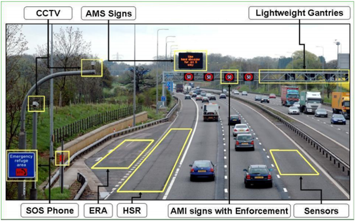
Active Traffic Management Systems. Key: CCTV = Closed-Curcuit Television; AMS = Advanced Message Sign; ERA = Emergency Rest Area; HSR = Hard Shoulder Running; AMI = Advanced Motorway Indicator.
Tachographs and fleet management systems can provide data on driver hours of service and vehicle speeds. The use of video cameras as an integral part of fleet management systems is becoming more common. The camera view may be of the forward roadway only or it may also extend to a cabin (driver) view allowing investigation of driver attention in the pre-accident period. Fleets typically use such data for feedback to drivers, driver training and investigation following an incident. The saving of data for a time window is typically automatically triggered by an accelerometer that detects rapid acceleration or deceleration.
So-called “blackbox” Event Data Recorders (EDRs) are mandated for other modes of transport such as civil aviation but are not yet required for road vehicles. The recorders provide enhanced quality and accuracy of accident data. Typically, they store recent data in short-term memory – and the memory store is replaced at frequent intervals. Once an event, such as airbag deployment, is detected, the data in the memory store is permanently saved. This will comprise information on the status of vehicle sensors and control systems which can be accessed from the vehicle’s Controller Area Network (CAN). Data can include information on speed, accelerator pedal position, brake activation, driver use of seatbelt, as well as use of on-board vehicle systems such as cruise control or speed limiter prior to and during an accident.
EDRs are already present in a large proportion of vehicles, including over 90% of light vehicles in the USA. There is a US standard for EDRs fitted in light vehicles (Code of Federal Regulations Title 49 part 563). It is intended to ensure that data from an accident is usable for accident investigation purposes and can assist in analysing the performance of advanced safety systems such as restraint systems. The standard specifies common requirements for EDRs in terms of vehicle information such as speed, accelerator position, brake application, engine speed and speed change through a collision. It also requires vehicle manufacturers to provide data retrieval tools. There has been extensive discussion, particularly in North America, about mandating the fitting of EDRs in all new light vehicles - but to date, no legislation has been enacted. (See Probe Data)
Reliable accident reporting systems have value in enhancing understanding of conflict and behavioural issues and in identifying common causes of accidents and developing effective countermeasures.
Procedures need to be put in place to store and archive relevant data from roadside systems. There are privacy issues associated with data stored by fleet management systems and in-vehicle Event Data Recorders. In some countries the consent of drivers may be needed to access the EDR information unless there are legal provisions that provide s of access in certain situations. (See Legal and Regulatory Issues)
Analysis of prior accident history can be used to guide decisions on the deployment of safety-related ITS systems – systems primarily targeted at reducing accident numbers and accident severity. The analysis can help identify what systems to install and where to install them. There is little benefit to road network operations from deploying systems and technologies where they are not needed - and where they will have little impact. For example in many countries the location of speed cameras is determined by considering the relationship between the number of speed violations and excessive numbers of accidents. A similar approach, focused on the relationship between accidents and violations, can be used to determine the best location for red light cameras.
High-quality accident databases and appropriate tools for data extraction and analysis are required to identify problem sites. Proper procedures need to be applied to site identification to avoid selecting sites that are not fundamentally unsafe but may be subject to random fluctuations in accident numbers from one year to another. This problem is known as “bias by selection” where the resulting observed “improvements” in performance are in large part the result of random variation (“regression-to-the-mean”).
Before deciding that an ITS solution is needed, a proper assessment needs to be made of the alternatives. Standard tools are cost benefit analysis (CBA) and cost effectiveness analysis (CEA). CBA evaluates whether the predicted monetised benefits outweigh the costs. CEA measures alternative interventions against success criteria - such as lives saved or improvement in quality-adjusted life years (QALY). The QALY measurement represents the gap between an ideal scenario where everyone lives into old age free of disease and disability and the real-life situation in the population. (See Project Appraisal)
Some cooperative systems, such as intersection collision avoidance systems, are particularly targeted at blackspots. (See New and Emerging Applications)
There is considerable literature on problem site identification in road safety. The standard technique is to apply the Empirical Bayes (EB) method, which considers both the regression-to-the-mean effect and the expected safety performance of a particular site, based on the safety performance of similar locations.
Practitioners in developing countries need to consider the reliability and consistent quality of the available accident data. Where toll roads exist, the data may be fairly complete, in contrast to other parts of the road network. In some countries, data may be recorded where the police have relatively easy access to the accident locations but coverage may be poor elsewhere.
A useful introduction to the Empirical Bayes (EB) method is provided by Hauer, Harwood, Council and Griffith (2002), Estimating Safety by the Empirical Bayes Method: A Tutorial, Transportation Research Record 1784. A preprint version of this paper can be found at http://ezrahauer.files.wordpress.com/2012/08/trbpaper.pdf.
Excess speed (above the limit) and inappropriate speed (too fast for the conditions) are major factors in road safety. Increased vehicle speed leads to both greater accident risk and a greater likelihood that the outcome will be more severe – more likely to result in serious injury or fatality.
The so-called “power model” provides a good rule of thumb on how road traffic speed relates to accident risk and severity. The consequence of a small increase in speed is a disproportionately high number of accidents. A good approximation is that injury accidents change in relation to the average speed of road traffic. Injury accidents change with speed squared (v2), serious injury accidents change with speed cubed (v3) and fatal accidents change with speed to the fourth power (v4). This means that reducing traffic speeds by even a small amount will have a large effect in reducing the severity of injuries.
The variants of the power model have been developed from data obtained from countries with comparatively safe roads. Countries with poor quality roads, vehicles with few safety features, a large proportion of two-wheelers and low levels of road user compliance with regulations - may experience a much steeper relationship between speed and accidents.
Variability and large differentials in speed cause disturbances in traffic flow and increase risk. For instance:
Speed management is defined by the OECD as “a set of measures to limit the negative effects of excessive and inappropriate speeds in the transport system.” This requires a strategic approach to the problem of speed - starting with setting appropriate speed limits for different categories and qualities of roads and putting in place a variety of measures that can be used to deliver compliance.
Speed management is generally a central part of a region’s road safety strategy because of the crucial role that speed plays in determining accident risk. Multiple stakeholders are involved, including central and regional government, road operators, the police and road authorities. (See Incident Response Plans)
The variety of measures used in speed management include:
ITS makes possible the use of in-vehicle systems to encourage drivers and riders to comply with speed limits and choose speeds appropriate to road conditions.
Intelligent Transport Systems have a significant role in delivering speed management. For certain types of application, they are crucial. For example, they make it possible to deliver:
Increasingly, both weather-related systems and controlled motorways tend to be fully automated. They involve a range of ITS technologies and systems using distributed sensors to capture and send information to central traffic control centres for display on roadside information panels – as well as speed cameras for enforcement. (See Weather Management)
With the growth of real-time communications into nomadic devices and vehicles, we are likely to see greater delivery of information and warnings conveyed within the vehicle directly to the driver. It is already the case that many commercial satellite navigation systems and navigation applications for smartphones provide information on speed limits and can be set to warn the driver about speeding. It is in the interests of road authorities to provide suppliers of digital road maps with up-to-date information on speed limits and in particular with timely information on changes to speed limits.
ITS technologies can assist in:
United Nations Road Safety Collaboration has produced Speed Management: A Road Safety Manual for Decision-makers and Practitioners. This is available on-line at http://www.who.int/roadsafety/projects/manuals/speed_manual/en/. Chapter 3 covers tools, including ITS tools such as Intelligent Speed Adaptation(See Intelligent Speed Adaptation).
Intelligent Speed Adaptation (ISA), also known as Intelligent Speed Assistance, brings speed management into the vehicle. The aim of ISA is to discourage or prevent speeding by informing drivers about the speed limit for a road and warning them about excess speed. The most sophisticated systems prevent speeding by way of an electronic speed limiter. The fundamental distinction is whether they are advisory or intervening:
Advisory ISA is already on the market — it is a feature in many commercial satellite navigation systems, although it is generally for the end-user to decide whether to implement the function. Manually set speed limiters are available in many vehicle models. No vehicle manufacturer currently offers a full intervening ISA.
Fully- intervening ISA has been trialled extensively in real-world driving (so-called Field Operational Tests). These trials have produced generally positive results in terms of behaviour, showing that the use of ISA in all its forms brings about a significant reduction in speeding. They also indicate a reasonable level of acceptance by users, even though users might feel somewhat disadvantaged by having ISA in that they can see other drivers travelling faster than they are.
Using well-validated models of the relationship between driving speeds and risk - calculations of the impact of ISA on accidents have been made. Probably the most comprehensive set of calculations is from trials conducted in the ISA-UK project during 2004-2006. The prediction is that an advisory ISA in general use, would save 3% of injury accidents and an intervening ISA would save 12% of injury accidents and 20% of fatal accidents.
In its strongest variant (an intervening version which cannot be overridden), the prediction is that ISA would deliver a 29% reduction in injury accidents. Applying the power model this translates into a 50% reduction in fatal accidents. [Shifting driver behaviour to virtually full compliance with speed limits can cut the number of fatal accidents in half – in a country with good driver compliance patterns. For countries with poorer levels of compliance, the impact would most likely be greater – if drivers accepted the technology. (See Speed Management)
ISA consists of two major elements or sub-systems – informing the driver (all systems) and controlling the vehicle (only applicable to intervening ISA). A visual display and speaker system also need to be provided. Where ISA is installed as original manufacturer’s equipment, the display and speakers are integrated into the dashboard.
The information part of ISA typically uses a digital road map, enhanced with speed limit information. This can be supplemented with a digital camera on the vehicle that reads speed signs to make up for any gaps in the map. It can also offer real-time information for locations such as work zones.
Digital map providers routinely collect speed limit information and can provide extensive coverage for many countries. Agreements are needed for data exchange between public authorities and commercial map providers to ensure that changes to speed limits are quickly incorporated into maps. One such initiative is the European Transport network ITS Spatial Data Deployment Platform (TN-ITS) which covers a range of road data including speed limits (http://tn-its.eu/).
Many new vehicles, both cars and trucks, currently feature driver-set speed limiters (cruise control) either as standard or as an option. Replacing the driver control with ISA works without driver intervention and is a straightforward technical step.
ISA is a mature technology and the purchase of cars with ISA or with ISA-like features is being promoted. Many fleet management systems incorporate ISA-like capability – with speed infractions by drivers being reported back to the fleet manager. This is known as “recording ISA”. Similar features are also included in many PAYD (Pay as you drive) or UBI (Usage Based Insurance) schemes.
The European Transport Safety Council (ETSC) has a Frequently Asked Questions (FAQ) section on Intelligent Speed Adaptation which provides a good summary of the current position on ISA implementation - http://archive.etsc.eu/documents/Intelligent_Speed_Assistance_FAQs_2013.pdf
Policing and enforcement have an important part to play in road network operations to improve road safety and to support the efficient use of road space. ITS provides the capability for automated detection and registration of traffic offences such as:
Camera-based ITS solutions can be used for vehicle access control, enforcement of low emission zones (“clear zones”) (See Environmental and Resource Issues) and traffic offence detection (over height, overweight), as well as moving vehicle offences (speeding). Pictures are automatically taken of vehicles/drivers that violate the rules and a fine is sent to the owner/driver.
Camera-based applications which incorporate Automatic Number Plate Reading (ANPR) include the prevention of through traffic on inappropriate roads (rat running) - such as bus only lanes, residential streets and short-cuts through hospital grounds. By installing ANPR at the control points, details of vehicles entering and leaving can be captured. The availability of a well-maintained and reliable up-to-date vehicle registration database is essential.
Automated enforcement systems for speed limit and traffic signal compliance have proven to be very effective in reducing fatalities and can create increased customer demand for speed alert systems. Many road authorities are now looking at the best ways to promote the deployment of ITS based automated enforcement systems on their roads. Special attention to enforcement on road sections with dynamic speed management (variable speed limits) is required.
Administrative arrangements and legal issues differ from country to country and will dictate enforcement methods and procedures. For example in some countries the vehicle owner is responsible for the offence whoever is driving; whereas elsewhere the police may have to prove who is the driver – so that the enforcement camera image has to show the driver’s face. Privacy issues relate to systems that either identify the driver (enforcement systems) or their location. These are often subject to legislation that limits the capture, use and storage of data (See Law Enforcement).
The European Union’s PEPPER project (2006-2008) is an example of a collaborative study which looked at police enforcement policy and programmes across European roads with the aim of improving its efficiency. (See http://www.vtt.fi/sites/pepper/en/police-enforcement-policy-and-programmes-on-european-roads)
PEPPER assessed several aspects of enforcement in relation to speeding, drink-driving and use of seat belts– and focused on:
Traditional forms of speed enforcement (such as Gatso wet film cameras) are being superseded by digital photography, eliminating the need to replace the film and requiring lower maintenance and operational costs.
Static speed enforcement measures (spot speeds) can cause rapid acceleration and deceleration as drivers apply their brakes in advance of cameras and then speed up. Average speed enforcement is enabled by Automatic Number Plate Recognition (ANPR) systems which identify vehicles at different positions on the network so that the average speed between two points can be measured. In this way, the speed across the entire length of a road can be enforced, to encourage compliance over longer periods, particularly through areas of temporary traffic management where operatives may be present.
A number of road safety benefits are associated with average speed enforcement. There are generally higher rates of compliance with speed limits with reductions in average and 85th percentile speeds (the speed exceeded by only 15% of drivers) and lower speed variability between vehicles – with consequential reductions in accident rates and in particular, serious and fatal injuries.
Most current enforcement technologies (such as speed warning devices) do not provide feedback to the driver on how they compare with others. Feedback based on collective measures of performance (such as the frequency and level of speeds in excess of the limit) can be significant in changing driver behaviour and improving compliance. The assumption is that most drivers will wish to improve their performance and conform to the actions of others. An ITS solution can use the individual data to provide drivers with an accurate overview of enforcement activity and encourage further compliance.
Spot Speeds
ANPR is a method that uses optical character recognition of digital images to read the licence plates on vehicles. The images are captured on cameras located in a mobile unit or built into law enforcement vehicles or from Closed Circuit Television (CCTV). The ANPR system cross-references the data against existing vehicle registration databases to determine whether the vehicle is untaxed, unlicensed or of any other interest to the police.
Camera errors can be as a result of:
Average Speeds
Average speed cameras operate using automatic digital technology. Cameras are mounted on columns at the side of the road. By placing the cameras at known points the speed of vehicles can be monitored along a length of road. The cameras are linked by cable or wireless and continuously capture images of vehicles. The number plates are read using ANPR and the average speed of the vehicle between the two cameras is calculated. If this exceeds the speed limit, an offence record is created and the owner contacted with reference to a database of vehicle registrations.
Despite the success of average speed cameras, their use of ANPR highlights a number of practical, social and political issues:
“Clock drift” is another phenomenon that may affect reliability, whereby the physical timing mechanisms that are part of the ANPR system as a whole are subject to errors. These can happen for a number of reasons, including temporary power cuts. The subsequent ANPR data may be ‘fast’ or ‘slow’. The set up on the systems can vary and some include an automatic clock readjustment process. The size of the timing errors can be anything from less than 2 minutes to over 8 minutes. This undermines public confidence in using ANPR for speed enforcement and evidence of a speeding offence.
Alcohol consumption, even in relatively small amounts, increases the risk of being involved in an accident for motorists and pedestrians. Alcohol not only impairs critical cognitive processes, such as vision and reaction time, it is also associated with impaired judgement. Road users under the influence of alcohol engage more in other risky behaviours such as crossing traffic in inappropriate places, or not using a vehicle seat-belt where madatory.
Research indicates that a considerable proportion of drivers, motorcyclists and pedestrians have alcohol in their blood in sufficient concentrations to impair their skills – whilst the probability of arrest while driving with an illegal blood alcohol level is low.
Traditional methods of reducing the prevalence of drink driving have included fines, prison sentences, vehicle impoundment and licence revocation – each has a downside. Prison for example is costly.
There is therefore an opportunity for ITS to play a part in the detection of drunken driving. Improvements in alcohol-sensing technology have led to the development of alcohol ignition interlocks. To operate a vehicle equipped with an interlock, the driver must first provide a breath specimen. If the breath alcohol concentration of the specimen is too high, the vehicle will not start.
Convicted drink drivers are sometimes offered the choice of a standard punishment (fine or points on their licence), or have the option for an alcohol ignition interlock to be fitted to their vehicle for a fixed period. Interlocks are typically fitted to vehicles of repeat offenders. The percentage of drivers who have interlocks installed is so low that the device has had little effect on the drink driving population as a whole.
In principle detection of alcohol can be achieved via odour sensors incorporated into the vehicle hardware (such as the gear shift) that can detect the presence of alcohol in perspiration. A warning can then be instigated via the navigation system, providing the driver with information on the nearest safe place to stop (e.g. a service station). The technology is still in development. For example sensors might be placed close to the driver’s face to minimise confusion with a passenger’s breath. Alternatively facial monitoring could be used although there could be some confusion with fatigue monitoring (eye blinks and closure).
Alcohol detection systems are still being developed and evaluated. As with all enforcement there are privacy issues – except where fleet managers have a no drink-driving policy in place as part of their terms and conditions of employment.
The transport of dangerous goods such as chemicals and dangerous products (known as hazardous materials in the USA or “HAZMAT”) - needs to be regulated in order to prevent accidents to people, infrastructure, other transport and the environment. Different regulations are in place across the world. The United Nations Economic Commission for Europe (UNECE) has issued Recommendations - which, for roads, is elaborated in a UNECE agreement. Although not legally binding, their recommendations are widely accepted internationally. ITS can help support these regulations – for example by monitoring the position of a vehicle, so it can be located efficiently and accurately if an emergency arises. (See Enforcement)
The position of a vehicle carrying hazardous goods can be tracked continuously, either actively or passively. In both cases, Global Navigation Satellite System (GNSS) is essential to identify the vehicle’s position.
A passive tracking system stores data on the vehicle’s location and other information (such as vehicle condition or container status) which can be examined retrospectively.
An active tracking system requires data to be sent by wireless communication to a control room for monitoring in real-time. In addition to location, further dynamic information (such as status of the truck or condition of the dangerous material) can be collected by the on-board unit. Active tracking is valuable in an emergency situation and also has wider benefits. For example:
Overloading a heavy goods vehicle has road safety implications but is also a major factor in the deterioration of road structure of the vehicle.
Safety may be compromised if an overloaded vehicle becomes unstable when driven at the limit of its safe performance. For example, braking distance increases with greater load which may lead drivers to underestimate stopping distances. Risk of tyre failure increases as they heat up under increased load. In addition, if a load is piled high, the raised centre of gravity increases the risk of vehicle rollover. The likelihood that a driver may lose control of the vehicle is greater when the vehicle is overloaded or the load is overweight, unbalanced or shifts its position.
Damage to roads by overloaded vehicles leads to higher maintenance and repair costs and shortens the life of a road. This places an additional burden on the road owner for maintenance and reconstruction. Other road users may carry the associated costs. Overloading also shortens a truck's service life and increases its operating costs and the need for unscheduled maintenance. (See Weight Screening)
There a number of ways of monitoring overloading:
Drivers rarely “just drive”. There are many different activities a driver engages with, in parallel with controlling the vehicle and maintaining a safe course. Some are considered fairly harmless (such as listening to the radio), whilst others have a more serious impact on driver performance (such as using a mobile phone to text or make a call).
Vehicle manufacturers offer a variety of in-vehicle “infotainment” systems ranging from navigation to email in addition to driver assistance systems such as lane departure warning. All are potential sources of distraction in addition to roadside information and distractions - including large LED advertising displays, Variable Message Signs, roadside advertisements, traffic incidents and accidents on the highway. (See Driver Support)
As well as leading to positive changes in driver behaviour and safety, ITS applications for driver safety can also lead to negative outcomes. Attention overload and driver distraction are two examples. The design of an ITS application may present information that is either too frequent or too complex for the driver to process without disrupting the primary task of driving. Other applications which automate or simplify driving may lead to the driver being distracted by non-driving tasks. (See Human Factors)
Real time monitoring of driver distraction is not mature enough to be used with confidence. Some vehicle manufacturers have developed “workload managers” which regulate the volume of information presented to the driver at any one time to minimise the risk of driver distraction. For example as a driver enters a roundabout, incoming phone calls are delayed the vehicle manoeuvre is completed. This is work in progress. Sophisticated on-board measurement of driver distraction via camera technology and even the monitoring of brain-wave patterns is being investigated.
Mobility is part of daily life. Anyone using the roads is at risk of injury or death in the event of a road accident. Some people are more at risk than others and are commonly referred to as Vulnerable Road Users (VRU). The term has been defined in different ways:
Transport policy makers and road authorities who are responsible for road safety strategies and policies at national and local level need to provide safe road infrastructure that integrates protection for vulnerable road users. ITS technologies can help through:
Vehicle manufacturers are also exploring vehicle protection systems for Vulnerable Road Users (VRUs). These are often based on forward looking cameras mounted on the vehicle, used in conjunction with other in-vehicle safety applications such as forward looking radars and Collision Warning. (See Warning & Control) Video: Inside Ford’s Pedestrian Detection System
Walking is an essential part of daily mobility (if only from a parked vehicle to reach the final destination). As traffic on the roads increases, the potential risk of vehicle-pedestrian collisions increases also. The World Health Organisation’s 2013 statistics show that 22% of traffic fatalities globally are pedestrians.
Vehicle speed is a key factor in pedestrian fatalities. The Australian Federal Office of Road Safety and the UK Department for Transport assessed the relationship between the two. The table below hows a dramatic increase in fatalities at higher impact speeds.
| Vehicle speed | Odds of pedestrian death |
|---|---|
|
20 mph |
5% |
|
30 mph |
37-45% |
|
40 mph |
83-85% |
The role of ITS applications for enhancing pedestrian safety on the roads include:
New ITS-based developments include:
The key to putting appropriate measures in place is to identify where interventions are needed - high risk accident zones and locations – and to review the effectiveness of available countermeasures. (See Accident Analysis)
WHO (2013) Pedestrian safety: a road safety manual for decision-makers and practitioners.
http://apps.who.int/iris/bitstream/10665/79753/1/9789241505352_eng.pdf
Encouragement of cycling as a mode of transport is one way of contributing to sustainable transport objectives. In most countries levels of cycling have declined with increased use of cars, vans and motorised two-wheelers – but an upward trend has been observed recently in highly urbanised areas such as Paris and London linked to deployment of ITS back-office support for city-wide bike hire schemes.
A significant barrier to achieving uptake of cycling are widely held concerns about road safety - due to the amount of traffic on the roads as insufficient provision of cycling-friendly infrastructure.
The role of ITS applications for enhancing cyclist safety include:
New developments to benefit cyclists include:
The key to putting appropriate measures in place is to identify sites which are of concern for cyclist safety such as problematic junctions and roundabouts – together with assessing user acceptance of specific solutions, whether they are cyclists, drivers or other road users including nearby residents.
Rutgersson (2013) A study of cyclists' need for an Intelligent Transport System. Masters dissertation. Chalmers University of Technology: Göteborg, Sweden.
http://publications.lib.chalmers.se/records/fulltext/183271/183271.pdf
Jordova et al (2012) Recommendations on standardisation, deployment and a research agenda. Deliverable D5.1 of the SAFECYCLE project.
http://www.safecycle.eu/cms_soubory/rubriky/85.pdf
De Jong et al (2012) State of the art applications to enhance the safety of cycling. Deliverable D2 of the SAFECYCLE project.
Children, elderly and disabled are particularly vulnerable to road accidents. These groups have less resilience to falls or collisions and may have limited mobility. They often rely on mobility aids – walking sticks, wheelchairs and pushchairs. Children in particular have a great propensity to be distracted, and when they gain independence they are often inexperienced in road use and its consequences.
The role of ITS applications that benefit the safety of these vulnerable road users include:
The key to putting appropriate measures in place is to identify installation locations where pedestrians are at risk – such as crossing points or junctions adjacent to schools, nursing homes, or a high concentration of disabled pedestrians.
Roadworks occur all the time on the network. Highway authorities and road operators carry out maintenance and improvement works such as road widening, resurfacing, bridge and gantry maintenance, white line painting, litter collection and gully emptying. The providers of utilities such as gas, electricity, water, sewage and telecommunications - also carry out maintenance and repairs to their infrastructure located alongside or below the road.
Road workers are commonly exposed to serious risk of accidents and fatalities. Vehicle speed is often a key factor in road worker fatalities. The role of ITS application in reducing these risks include:
The key is to make drivers aware of the presence and vulnerability of road workers. (See Work Zones)
Safety at street works and road works: a code of practice 2013 (UK)
US Department of Transportation: work zone mobility and safety program
Working animals include guide dogs that help the visually impaired people and horses carrying riders or pulling carts that share the roadway. All are at risk of accidents, many of which are preventable.
There is very little reported experience of technology solutions for working animals. A potential application – for guide dogs and visually impaired people - would be cooperative systems which combine geo-location with communications - for example:
This could be achieved through a combination of Global Positioning Satellites and Radio Frequency Identification. A similar concept might be appropriate for horse riders and horse drawn carts – enabling communication between the equipment worn on the animal and the road infrastructure.
Road users interact with their surrounding environment. Information and safety warnings are provided to drivers during a journey in various ways:
The concept of the “Self-Explaining Road” builds on the interaction of the road user with the environment – by promoting the idea that roads should be understandable to the road user. This is achieved through traffic engineering design supported by clear, consistent and readable roads signs and information to road users to guide them intuitively. Safe design is aimed at encouraging safe road user behaviour.
Modern signing systems have been used since the beginning of the 20th century. Road signs serve a common purpose: to communicate information or provide warnings to road users. Until the 1970s most signs were static. Today dynamic signs are widely used – they exploit information and communication technology and are a key component of ITS as part of the process of bringing together information collection, its integration and dissemination.
Early models of dynamic signs used rotating panels or lamp matrix signs for displaying directional/diversional information or advisory speed limits. More recent models allow greater flexibility in the range of information that can be displayed to road users – such as traffic conditions, incident warnings and road safety campaign messages.
One of the main purposes of dynamic signs is for traffic management – to manage incidents and mitigate their impact – by providing warnings of incidents and diversion advice and regulating traffic flow through variable speed limits. (See Use of VMS)
There are three major groups of stakeholders in the provision of safety information and warnings across the road network:
There are several aspects to the design of information signs and warning systems for the road operators to take into account before putting in place solutions to specific problems:
Information overload refers to the situation where there are too many signs along a stretch of road or at a single location. Dynamic signs may provide advantages over static sign if the display can be turned off when not needed (for example weather related warnings for ice or flooding). They can also be made to activate on detection of an approaching vehicle – usually in response to excess speed to get the attention of the individual driver.
Driver awareness of messages and their compliance can vary considerably and are influenced by the content of the message, its context and the road user’s previous experiences. Poor management of information signs can lead to lack of confidence – for example failure to remove a warning message when a traffic incident has cleared.
Driver attention is affected by the format of the display. Text messages tend to require greater levels of attention than symbols or pictograms. Drivers generally have a preference for pictograms although they are not necessarily always understood. Signs which change in real-time also impose higher attention demands compared to fixed signs. Readability and comprehensibility are affected also by the content of the message and how it is formatted. Splitting a long message into two short lines instead of one can shorten the response time – as can using a two-coloured display.
Design of text based dynamic signs is constrained by the limited space available which constrains the length of the message. Drivers tend to read messages in a series of short glances. The time frame available between first seeing the message and passing by may be quite short, even at low speeds. Prevailing driving conditions will influence how much attention the driver is able to give to reading and understanding the message.
Standardisation of static signs has been developed over a long period beginning with the Geneva Convention on the Unification of Road Signals, 1931. Dynamic signs, by contrast, are not yet standardised to the same extent – at either the national or international level.
Queue warnings are an effective contribution to managing traffic on high speed roads. They serve three objectives:
Effective queue warnings for network management require:
Queue warning systems therefore rely on rapid incident detection and warning technologies which:
In addition to road-based solutions, automotive manufacturers are developing collision warning systems that make use of on-board radar and sensors to detect obstacles (such as stationary vehicles ahead) to warn the driver or activate autonomous braking.
Cooperative vehicle systems communications - car to car (C2C) or car to infrastructure (C2I) - are able to warn drivers well ahead of an incident or queues forming (See Warning and Control Systems).
Queue warning systems (See http://mobility.tamu.edu/mip/strategies-pdfs/active-traffic/executive-summary/queue-warning-1-pg.pdf)
Portable End-of-Queue Warning Systems (See http://tti.tamu.edu/enhanced-project/facilitating-deployment-decisions-of-highly-portable-end-of-queue-warning-systems/)
The reason for deploying broken-down vehicle warning systems is to prevent rear-end collision and secondary collisions. They follow similar principles and use similar technologies as queue warning systems:
eCall is a European collision notification system aimed at summoning rapid assistance to motorists involved in a collision anywhere in the European Union countries. It uses GPS and digital cell-phone communications (such as GSM) to automatically initiate a 112 emergency call to the nearest emergency centre. It transmits the exact geographic location of the accident scene and other data. Such services are valuable for saving lives – in particular for single vehicle accidents in rural/remote areas. (See http://www.heero-pilot.eu/view/en/ecall.html and DRIVE C2X project http://www.drive-c2x.eu/use-03)
Breakdown Safety Strategy: A way forward. September 2012. Transport for NSW, Australia. (See http://www.mynrma.com.au/media/rms_breakdown_safety_strategy.pdf)
Road-side animal detection systems are deployed in some countries to prevent crashes involving large animals. There are potential dangers from free roaming cattle, wild horses, elephants, moose, kangaroos, bears and reindeer. The systems alert drivers to potential collisions with animals and rely on radar, lasers and other imaging techniques to detect the presence of animals on the roadway.
There are broadly two approaches to detection:
False alarms are the main problem, triggered by wind, rain or overgrown vegetation. Sensors can be adjusted, but it is very difficult eliminate false alarms completely whilst still ensuring that the target animals are detected. The frequency of false alarms should be monitored and adjustments made to the detection sensitivity of sensors – for example in advance of adverse weather conditions or in different seasons.
Sharafsaleh, M. and Huijser, M. (2012) Evaluation of an animal warning system effectiveness. California PATH, Richmond, CA, USA. Report number UCB-ITS-PRR-2012-12. (See http://www.dot.ca.gov/newtech/researchreports/reports/2012/2012-06_task_2090-tsm.pdf)
Ontario Ministry of Transportation, Canada. (See http://www.mto.gov.on.ca/english/safety/wildlife.shtml)
Bozeman Pass Wildlife Linkage and Channelization and Highway Safety Studies (See http://www.mdt.mt.gov/research/projects/env/boz_wildlife.shtml)
“Cooperative Systems” use communication between vehicles and between vehicles and the infrastructure (roadside equipment and traffic control centres) to provide drivers and other road users with real-time information. Vehicle-to-vehicle (V2V) communication applications include Cooperative Cruise Control and vehicle platooning (where vehicles are coupled into platoons with an “electronic tow-bar”). (See Coordinated Vehicle Highway Systems)
Vehicle-to-Infrastructure (V2I) applications have an important role to play in road safety by gathering, processing and exchanging information on traffic and road conditions from different sources on the network (locally and regionally) to develop information warnings and vehicle control instructions. For example vehicles can be alerted to slippery road conditions where the trigger might be icy road sensors at an exposed location or a skid registered by a vehicle.
Currently cooperative systems tend to be expensive. That is because the technology requires high bandwidth and very reliable and rapid (low latency) communications - which are costly. Specialised wireless communication, known as DSRC (Dedicated Short Range Communications) is potentially the high-end emerging standard. It uses a microwave or infrared communications with added security features. It is likely that DSRC cellular communications for V2I/I2V systems and services, will only be economically feasible in so-called "hot spots" of the road network such as tunnels, accident black spot intersections, signal-controlled intersections.
Besides the cost, a major obstacle to the use of cooperative systems, particularly V2V systems, is that there is little benefit to early adopters. Unless there are other equipped vehicles with which to communicate, the technology cannot interact. This is in contrast to autonomous systems such as Forward Collision Warning or Lane Departure Warning, where the equipment can have immediate benefit for the driver.
Cooperative Systems in the USA
The United States National Highway Traffic Safety Administration (NHTSA) has announced that it is considering requiring new vehicles to have connected vehicle (V2V) capability using DSRC. The expectation is that mass production will lower the cost of the V2V communication units and that government will develop a programme for installing DSRC roadside infrastructure.
V2V technology has the potential to be fused with existing vehicle safety features to further improve the effectiveness of many crash avoidance safety systems currently being developed and implemented in the vehicle fleet - and will serve as a building block for a driverless vehicle. Vehicles equipped with V2V technology could also enable the development of a wide range of mobility and environmental benefits based on vehicle-to-infrastructure applications and other V2V applications that can enhance traffic flow in many ways. V2V technology does not involve collecting or exchanging personal information or tracking drivers or their vehicles.
There are also moves to develop cooperative systems that use readily available technologies such as GPS combined with 3G and 4G mobile communications. One example is TomTom’s “Jam Ahead Warning” system, which alerts drivers to slow-moving traffic ahead of their current position. The system uses the real-time speed profile of users of TomTom navigation devices that are fitted with mobile data communications. The system identifies in real-time when traffic speeds are unusually slow and broadcasts an alert to other vehicles fitted with TomTom units in the locality. The advantage of autonomous systems such as this is that they can be implemented immediately without the requirement for installing expensive dedicated communications technology and infrastructure.
Other cooperative systems being trialled use roadside equipment to communicate with drivers. An example is intersection collision warning. Many proposed applications of cooperative systems are comparable to current use of Variable Message Signs. There is scope also for the development of safety applications based on Human-to-Vehicle (H2V) communications.
Safety at unsignalised intersections can be a major concern. Intersection collisions are one of the most common types of crash and tend to be severe particularly on rural roads. That is because collision speeds are often high and occupants are less well protected against side impacts compared to frontal collisions. The high speed of main-road traffic can exacerbate the situation.
Many rural intersections use static stop signs or give-way (yield) signs to control side-road traffic. The driver has to judge when there is a safe gap to join the main road traffic. Only the nearside gap needs to be assessed when the driver is not crossing the near-side traffic flow. Where the driver needs to cross the traffic flow, the task becomes more difficult. Multilane roads increase the difficulty.
Intersection collision warning systems use multiple sensors installed at the roadside to track vehicles as they approach, linked to sophisticated algorithms that determine whether gaps in the traffic are safe or unsafe (above or below a critical threshold). Signs to help the driver decide whether to make the manoeuvre are located where they can be seen by drivers at the stop or give-way sign – such as in the photograph in the box below.
Cooperative Intersection Collision Avoidance System (CICAS)
The University of Minnesota has developed the Cooperative Intersection Collision Avoidance System (CICAS) to improve safety of vehicles turning into or crossing rural divided highways. The initial development was in a driving simulator, followed by real-world implementation.
CICAS informs drivers at stop-signs when gaps between vehicles approaching on the main road are not large enough - see http://www.its.umn.edu/Research/FeaturedStudies/intersections/cicas.html.
The warning system is deployed at three intersections in Minnesota and one in Wisconsin - at high-risk locations. The Minnesota Department of Transportation is rolling out a refined version of the system to intersections across the state (2012-2015). It is known as the “Rural Intersection Conflict Warning System” (RICWS).
")
The layout of a warning sign at a trial location (source: University of Minnesota, ITS Institute)
Detailed information on the development of CICAS can be found at http://www.its.umn.edu/Research/ProjectDetail.html?id=2006050.
Currently most vehicle protection systems for Vulnerable Road Users (VRUs) are based on forward looking cameras mounted on the vehicle, used in conjunction with other in-vehicle safety applications such as Forward Collision Warning. As mobile communications mature at a rapid rate there is potential to develop safety applications based on Human-to-Vehicle communications. (See Vulnerable Road Users(ITS & Road Safety) and Vulnerable Road Users(Human factors)
To be reliable, the technology needs to be able to detect, classify and track relevant objects and disregard false alerts. The technology also needs to be readily accessible - at an acceptable cost for the user, wearable, easy to use and have low power consumption. In addition, the technology needs to cope with complex situations where people are obscured by other objects such as parked vehicles. In-vehicle equipment must have the ability to detect pedestrians or cyclists at intersections where a high proportion of incidents occur.
If Human-to-Vehicle communication systems are to be successful, the take-up needs to be relatively high. The technology is near-market so there is need for decisions on the appropriate user communication interface. For example:
Human-to-Vehicle Communication Developments
Approaches which combine video detection on the vehicle with real-time positioning systems for the vulnerable road user are being developed to provide warnings of each other’s presence. For example cooperative sensor technology via RFID tags can be integrated into school bags, clothing, helmets or mobile phones. In-vehicle location devices can transmit a continuous query to the RIFID tags to obtain information on the location, trajectory and speed of the road user. The objective is to calculate risk and warn of a possible collision. An example is Japan’s Pedestrian Information and Communication System to enable the elderly and the disabled to move around safely.
See: http://www.utms.or.jp/english/system/pics.html
Smart phones offer another promising platform and a communication interface for new applications.
Privacy issues – which may be sensitive for some user groups, such as children and vulnerable adults - will need to be addressed. Whilst a RFID tag may not identify a specific person, public concerns may be high and lead to low uptake of applications.